





Description
Product Introduction & Engineering Value
The Allen Bradley 1756-RM is a ControlLogix redundancy module designed for high-availability controller architectures. It manages communication between paired ControlLogix chassis, allowing a secondary controller system to maintain synchronization with the primary controller and assume control when required.
For critical automation systems, controller redundancy is not achieved by simply installing two processors. The complete architecture requires matched chassis configurations, compatible controllers, redundancy modules, firmware alignment, and correct synchronization cabling. The 1756-RM remains an important replacement component for installed ControlLogix redundancy systems.
Technical Specifications
| Specification | Details |
|---|---|
| Manufacturer | Allen Bradley / Rockwell Automation |
| Catalog Number | 1756-RM |
| Product Family | ControlLogix |
| Module Type | Controller Redundancy Module |
| Mounting Location | ControlLogix chassis, any available slot |
| Slot Width | Single slot |
| Synchronization Interface | Fiber optic |
| Compatible Controllers | ControlLogix 5560 and 5570 families |
| Compatible Chassis | 1756-A4, 1756-A7, 1756-A10, 1756-A13, 1756-A17 |
| Fiber Cable Options | 1756-RMC1, 1756-RMC3, 1756-RMC10 |
| Current Draw @ 5.1V DC | 1.2 A |
| Current Draw @ 24V DC | 120 mA |
| Power Dissipation | 9 W maximum |
| Operating Temperature | 0°C to 60°C (32°F to 140°F) |
Field Application & The “Trench” Experience
A chemical production facility operated a continuous process unit where an unexpected PLC controller failure could force a lengthy shutdown. The existing ControlLogix architecture used two identical controller racks with 1756-RM modules maintaining synchronization between the primary and secondary systems.
During scheduled maintenance, one redundancy module reported communication faults. The maintenance team replaced the 1756-RM, verified the fiber link, checked synchronization status, and confirmed that both controller chassis returned to a qualified redundant state before placing the system back into service.
The field lesson: redundancy hardware is rarely touched during normal operation, which means configuration drift and aging components can become hidden risks.
Typical application scenarios:
1. Continuous Chemical Process Control
Maintaining controller availability for reactors, blending systems, and process sequencing.
2. Power Generation Auxiliary Systems
Supporting turbine auxiliaries, balance-of-plant controls, and monitoring systems.
3. Large Manufacturing Lines
Protecting production equipment where controller downtime creates significant recovery costs.
Transparency SOP: QA & Testing
A 1756-RM inspection process should include:
1. Physical Condition Review
- Verify catalog number and hardware label.
- Inspect chassis connector pins.
- Check fiber-optic port condition.
2. Power-Up Verification
- Install in a compatible ControlLogix chassis.
- Confirm module startup behavior.
- Check LED status indicators.
3. Redundancy Communication Test
- Verify fiber communication link.
- Confirm redundancy module recognition.
- Check synchronization status with a compatible controller pair.
A tested New Surplus or refurbished 1756-RM should include inspection records showing functional verification before shipment.
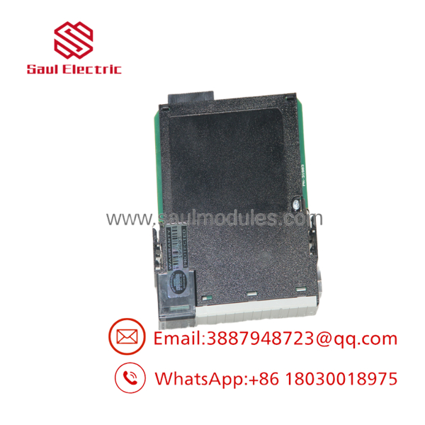
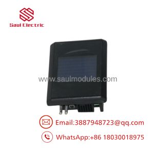
- 1756-RM
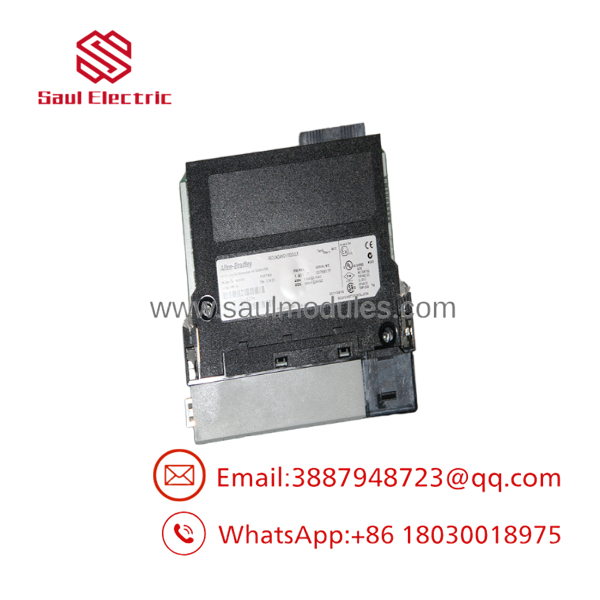
- 1756-RM
The Veteran’s Tech Trap Guide
⚠️ Do not mix redundancy module generations without checking compatibility.
A 1756-RM replacement is not automatically interchangeable with later modules such as 1756-RM2 or newer redundancy platforms. Firmware, controller family, and system architecture must match.
⚠️ The two redundant chassis must match.
Different controller firmware, chassis layouts, communication modules, or project configurations can prevent synchronization.
⚠️ Fiber cable condition matters.
A damaged or contaminated fiber connection can appear as a redundancy module failure. Always inspect the optical path before replacing hardware.
PRO TIP: Before removing a 1756-RM from a running system, record:
- Primary/secondary chassis configuration
- Controller firmware revisions
- Redundancy module firmware
- Fiber cable model and length
- Current synchronization status
Dynamic FAQ
1. What is the Allen Bradley 1756-RM used for?
The 1756-RM is a ControlLogix redundancy module used to synchronize paired controller chassis and support redundant controller operation.
2. Does the 1756-RM contain a processor?
No. The 1756-RM does not execute control logic. It manages redundancy communication between two ControlLogix controller systems.
3. What controllers are compatible with the 1756-RM?
The module supports ControlLogix 5560 and 5570 controller families when configured as part of a supported redundancy system.
4. Can a 1756-RM replace a 1756-RM2?
Not directly. The replacement depends on controller generation, firmware compatibility, redundancy architecture, and existing system documentation.
5. What should be checked before installing a replacement 1756-RM?
Verify:
- Controller model compatibility
- Firmware revision
- Chassis configuration
- Fiber-optic cable condition
- Redundancy project settings
- Studio 5000 / RSLogix configuration
6. Is a New Surplus 1756-RM tested before shipment?
A qualified supplier should perform visual inspection, power-up verification, LED diagnostic checks, and redundancy communication testing before shipping the module for industrial service.

 Start Chat


