





Description
Product Introduction & Engineering Value
The 1794-OW8 is the FLEX I/O choice when the field load does not fit a conventional solid-state DC output architecture. Its eight Form A relay contacts can switch both AC and DC loads, while the isolated relay construction allows each output circuit to be electrically separated from the other output circuits.
That flexibility comes with a tradeoff: relay outputs are mechanical devices. Rockwell specifies a maximum switching frequency of 0.3 Hz at rated load, so this module belongs on discrete control duties—not high-frequency pulse generation.
Technical Specifications
| Specification | 1794-OW8 |
|---|---|
| Module type | FLEX I/O relay output |
| Number of outputs | 8 |
| Relay configuration | Form A, normally open |
| Output isolation | Isolated |
| Supply voltage | 24 VDC |
| Relay contact rating | 250 VAC, 2 A resistive |
| DC contact rating | 5–30 VDC, 2 A resistive |
| AC switching | 120/240 VAC, 50/60 Hz |
| Maximum output delay | 10 ms OFF-to-ON / 10 ms ON-to-OFF |
| Initial contact resistance | 30 mΩ |
| Maximum switching frequency | 0.3 Hz at rated load |
| Expected contact life | 100,000 operations minimum at rated loads |
| FlexBus current | 35 mA at 5 VDC |
| Module power dissipation | 5.5 W maximum |
| Operating temperature | 0–55 °C (32–131 °F) |
| Dimensions | Approximately 94 × 94 × 69 mm |
| Terminal bases | 1794-TB2, TB3, TB3S, TBN, TBNF |
Rockwell’s installation instructions specify the eight isolated Form A relays, 24 VDC module supply, 250 VAC/2 A resistive rating, 5–30 VDC/2 A resistive rating, 10 ms maximum switching delay, 100,000-operation minimum contact life, and 0–55 °C operating range.
Electrical Ratings That Matter
For resistive loads, the relay contacts are rated at 2.0 A at 250 VAC and 2.0 A at 5–30 VDC. Inductive loads have lower allowable steady-state ratings depending on voltage and load characteristics. For example, Rockwell specifies 0.98 A steady-state at 5–30 VDC with L/R = 7 ms.
The module also has an approximately 1.2 ms mean contact bounce time. This is another reason not to treat a relay output as a high-speed solid-state switching point.
Field Application & The “Trench” Experience
A packaging line uses FLEX I/O to control a group of auxiliary devices: motor contactors, pilot relays, pneumatic-valve enable circuits, and several AC-operated indicators. One output module fails after years of service.
The replacement looks straightforward until the engineer checks the wiring. The failed module is a 1794-OW8, not a 1794-OB16 or other DC transistor-output module. The loads include both AC and DC circuits, making the relay architecture important. After replacing the module and checking each circuit individually, the engineer discovers that one contactor coil has excessive transient behavior. The coil suppression is corrected before the new module is placed back into continuous service.
The lesson: with relay I/O, don’t stop at “the output switches.” Check the actual load type and switching duty.
Specific application scenarios
- Motor starter and contactor control where isolated relay contacts are preferred.
- AC solenoid or valve control in process skids.
- Interposing relay control between FLEX I/O and higher-voltage field circuits.
- Packaging-machine auxiliary devices requiring mixed AC/DC discrete outputs.
- Legacy machine retrofits where existing field wiring already expects dry-contact-style switching.
Transparency SOP: QA & Testing
For New Surplus or Refurbished 1794-OW8 inventory, testing should focus on relay operation rather than simply checking the status LEDs.
- Catalog verification — Confirm the module is specifically marked 1794-OW8 and check the Series designation.
- Physical inspection — Examine the housing, FlexBus connector, terminal-base interface, label, and indicator LEDs.
- Power-up verification — Install the module on a compatible FLEX I/O terminal base and verify normal startup.
- Eight-point functional test — Command every relay output and confirm mechanical contact operation.
- Contact verification — Measure continuity and open-circuit behavior with controlled test equipment.
- Load simulation — Test representative AC and DC loads within the manufacturer’s specified ratings.
- Final QA record — Record catalog number, Series, test status, condition, and warranty.
Rockwell currently lists a one-year standard warranty for the 1794-OW8.
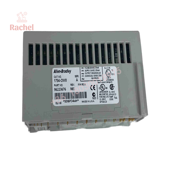
1794-OW8
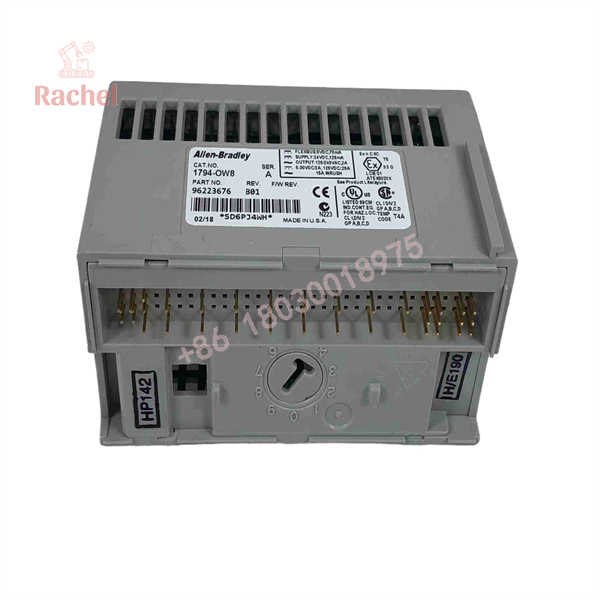
1794-OW8
The Veteran’s Tech Trap Guide
⚠️ Trap #1 — Treating it like a transistor output.
The 1794-OW8 uses mechanical relay contacts. Rockwell specifies a maximum switching frequency of one operation every three seconds at rated load. It is not appropriate for rapid repetitive switching.
⚠️ Trap #2 — Ignoring inductive-load ratings.
The 2 A resistive rating does not mean every 2 A inductive load is acceptable. Contactors, solenoids, and coils can produce substantial transient energy. Check the applicable inductive-load rating and provide appropriate suppression.
⚠️ Trap #3 — Forgetting the terminal base.
The module mounts to a compatible FLEX I/O terminal base; the module itself is not wired like a conventional standalone PLC output card. Rockwell identifies TB2, TB3, TB3S, TBN, and TBNF terminal bases for this module.
PRO TIP: If a replacement 1794-OW8 repeatedly develops welded or intermittent contacts, don’t automatically blame the module. Measure the actual load current, inrush, switching frequency, and suppression arrangement.
Dynamic FAQ
What is the Allen-Bradley 1794-OW8?
The 1794-OW8 is an 8-point FLEX I/O isolated relay output module using normally-open Form A contacts.
What voltage can the relay outputs switch?
For resistive loads, the contacts are rated for 250 VAC at 2 A and 5–30 VDC at 2 A. The allowable rating varies for inductive loads.
Are the eight relay outputs isolated?
Yes. Rockwell specifies one group of eight isolated Form A electromechanical relays.
Can the 1794-OW8 switch solenoids and contactors?
It can be used with suitable inductive loads, but the load must remain within the applicable inductive ratings. Coil suppression and inrush characteristics should be evaluated during application engineering.
Is the 1794-OW8 suitable for high-speed switching?
No. Rockwell specifies a maximum switching frequency of 0.3 Hz at rated load, or approximately one operation every three seconds.
What terminal base does it use?
Compatible terminal bases include 1794-TB2, 1794-TB3, 1794-TB3S, 1794-TBN, and 1794-TBNF.
Is the 1794-OW8 still available?
Rockwell currently lists the product as Active Mature and indicates that a replacement is available.
How do I verify New Surplus authenticity?
Check the 1794-OW8 catalog number, Series marking, manufacturer label, physical condition, and relay operation. For a surplus unit, a point-by-point continuity test on all eight relay channels provides substantially more useful verification than a visual inspection alone.
What warranty applies?
Rockwell currently lists a one-year standard warranty for the 1794-OW8. For New Surplus or Refurbished inventory from an independent supplier, verify the supplier’s own warranty terms before ordering.

 Start Chat


