





Description
Core Product Summary
The ALSTOM FV223-M2 is a diode failure detection module for the GECOSTAT generator excitation system. It monitors the rectifier diodes in a brushless exciter and identifies open-circuit or short-circuit diode failures. These faults can disrupt excitation performance and, if left undetected, contribute to generator operating problems.
The module provides fault indication and relay-based alarm signaling for integration with the excitation control and plant monitoring systems. Its diagnostic role helps maintenance personnel identify diode-related faults without treating the module as the primary excitation regulator.
The FV223-M2 is used in legacy generator excitation installations. Before replacing it, verify the full model designation, nameplate details, terminal arrangement, supply requirements, and compatibility with the existing GECOSTAT system. Electrical and environmental values should be confirmed against the documentation for the installed version.
Key Technical Specifications
| Parameter | Specification |
|---|---|
| Manufacturer | ALSTOM Electrical Machines / GECOSTAT |
| Model | FV223-M2 |
| Product type | Exciter diode failure detector |
| System family | GECOSTAT excitation system |
| Primary function | Monitoring brushless-exciter rectifier diode faults |
| Faults monitored | Open-circuit and short-circuit diode failures |
| Monitored components | Excitation rectifier bridge diodes |
| Power supply | 24 VDC reported in supplier documentation |
| Permissible supply range | 18–30 VDC reported by one supplier; verify against the nameplate |
| Fault indication | Status LEDs |
| Fault output | Relay-contact alarm output |
| Local testing | Built-in test function reported in supplier documentation |
| Mounting | Confirm the installed rack and mounting arrangement |
| Operating temperature | Verify against the applicable technical documentation |
| Dimensions and weight | Confirm from the physical unit or original drawing |
Specification note: Public listings provide inconsistent mechanical and environmental data. Unverified dimensions, weight, and temperature limits are intentionally omitted.
Engineering Selection Highlights
- Dedicated diode monitoring: Designed to detect failures in the rectifier diodes of a brushless generator exciter.
- Fault-state indication: Status LEDs help identify detected diode faults and module power status.
- Alarm signaling: Relay-contact output allows fault information to be passed to the wider excitation or plant monitoring system.
- Generator protection support: Early detection of rectifier diode problems can help maintenance teams investigate excitation abnormalities.
- Legacy system compatibility: Intended for the GECOSTAT excitation architecture rather than universal PLC applications.
- Replacement verification: Exact supply, connections, and system configuration should be checked before installation.
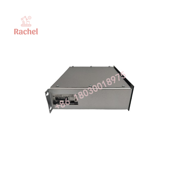
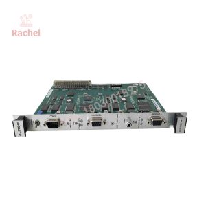
FV223-M2
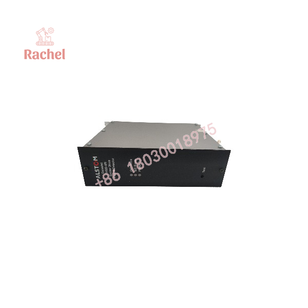
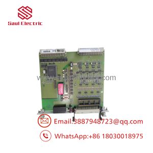
FV223-M2
System Compatibility and Integration Requirements
| Integration area | Verification required |
|---|---|
| Excitation system | Confirm compatibility with the installed GECOSTAT system. |
| Rectifier bridge | Verify the monitored diode arrangement and associated sensing connections. |
| Power supply | Check the actual unit’s rated voltage and polarity. |
| Fault relay | Confirm contact ratings and the receiving alarm circuit. |
| Indication and testing | Verify the expected LED states and test procedure using the correct manual. |
| Control-system interface | Check how fault signals are wired to the excitation controller or plant monitoring system. |
| Mounting | Match the original rack, connector, and mechanical arrangement. |
| Replacement configuration | Compare the model designation and any version or serial information. |
The FV223-M2 should not be substituted with a generic diode-monitoring device based only on its function. The sensing arrangement, fault logic, output contacts, and excitation-system wiring must be compatible.
Dimensions, Mounting, and Connection Notes
Verified dimensions and terminal assignments for the exact FV223-M2 version are not established here.
Before installation:
- Record the complete model and serial number from the nameplate.
- Photograph the module, connectors, terminal labels, and existing mounting arrangement.
- Verify the supply voltage and polarity against the original documentation.
- Trace the diode-monitoring connections and relay alarm wiring before disconnecting the unit.
- Confirm the correct rack position and any mechanical or electrical keying.
- Follow the generator and excitation-system isolation procedures before removing the module.
Because the FV223-M2 is part of a generator excitation monitoring and protection arrangement, commissioning should include the manufacturer’s prescribed functional checks. Do not assume that a power-on LED alone confirms correct diode-fault detection.
Detailed Product Overview
Diode fault detection
A brushless excitation system uses rectifier diodes to convert the exciter’s AC output into DC for the generator rotor field. A diode failure can impair rectification and cause excitation abnormalities. The FV223-M2 monitors the relevant diode circuit to detect failure conditions, including open-circuit and short-circuit faults.
Fault indication and alarm signaling
The module provides visual status indication and a relay-contact fault output, according to available product documentation. The relay output can be integrated into a compatible excitation alarm or plant monitoring circuit. The actual contact arrangement, ratings, and alarm logic must be confirmed from the original wiring diagram.
Role in the excitation system
The FV223-M2 is a monitoring and fault-detection component. It should not be confused with the main excitation regulator, field-current controller, or a general-purpose protection relay. Its signals support the wider system’s fault response and maintenance process.
Maintenance and replacement
When a diode fault is reported, investigate the rectifier bridge and associated sensing circuits in accordance with the generator manufacturer’s procedures. Confirm the condition of the monitoring wiring and module supply before concluding that the detector itself has failed.
For replacement, preserve the original connections and configuration records. After installation, perform the specified diagnostic or functional test and verify that fault indication and relay signaling work as intended. Any testing involving the excitation system must be conducted by qualified personnel under approved plant procedures.
Applications and System Role
The FV223-M2 is intended for generator excitation systems that use a brushless exciter with a rotating rectifier bridge.
Typical system-level applications include:
- Synchronous generator excitation systems
- Industrial power-generation installations
- Generator rectifier diode condition monitoring
- GECOSTAT excitation system maintenance
- Troubleshooting of excitation-related alarms
The module’s exact role depends on the excitation system’s design and how its fault outputs are connected to the generator control and protection equipment.
Frequently Asked Questions
Q1: What is the ALSTOM FV223-M2?
It is a GECOSTAT exciter diode failure detector used in generator excitation systems.
Q2: What faults does the FV223-M2 monitor?
Available documentation identifies open-circuit and short-circuit faults in the brushless exciter’s rectifier diodes.
Q3: Does the FV223-M2 provide a fault output?
Yes. Product listings identify a relay-contact fault output. Confirm the precise contact arrangement and rating against the applicable documentation.
Q4: What power supply does it require?
Supplier documentation reports a 24 VDC supply, with one listing specifying an operating range of 18–30 VDC. Verify the actual unit’s nameplate and manual before energizing it.
Q5: Is the FV223-M2 an excitation regulator?
No. It is identified as a diode failure detector. It monitors rectifier diode conditions rather than serving as the primary generator excitation regulator.
Q6: How can I confirm the correct replacement?
Match the FV223-M2 designation, nameplate details, connectors, supply requirements, monitoring connections, and relay output wiring to the existing installation.
Q7: What should be provided for a replacement quotation?
Provide the full model number, serial number, nameplate photograph, quantity, required condition, and details of the generator excitation system.

 Start Chat


