





Description
Product Introduction
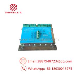
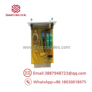
The Autronica BSU-50-V3 is a dedicated serial communication interface module developed for Autronica’s legacy BS-100 series fire alarm control panels. Installed directly inside the main control chassis, this card handles high-integrity data traffic moving between the central processing unit and remote equipment like repeater panels, mimic displays, graphics systems, and vessel management networks.
Revision ‘V3’ brings enhanced optical isolation and noise suppression compared to older hardware spins, protecting the central panel bus from external electrical ground loops and signal degradation over long cable runs. The BSU-50-V3 relies on physical DIP switches for baud rate selection and board addressing. For marine vessels and industrial sites relying on legacy BS-100 infrastructures, finding an exact match BSU-50-V3 board is critical to fixing system comm faults without undergoing an expensive total system replacement.
Key Technical Specifications
| Parameter | Specification |
| Manufacturer & Part No. | Autronica BSU-50-V3 (116-BSU-50-V3) |
| System Compatibility | Autronica BS-100, BS-80, BX-10 Panels, BU-100 Repeaters |
| Interface Channels | Dual Serial Communication Ports |
| Supported Protocols | RS-232C, RS-422, or RS-485 (Configured via jumpers/DIP switches) |
| Operating Voltage | 24 VDC (Powered via internal panel ribbon backplane) |
| Galvanic Isolation | Opto-isolated communication lines (Up to 500V protection) |
| Baud Rate Options | Selectable via DIP switch (Typically 1200 to 9600 Baud) |
| Termination Interfaces | Pluggable green screw-terminal headers & ribbon connectors |
| Status Indicators | Onboard Tx/Rx LED activity indicators per channel |
| Conformal Coating | Marine-grade protective varnish against salt air and moisture |
Application Scenarios & The “Trench” Experience
The Marine Engineer’s 2 AM Emergency
You’re the chief electrician on a container vessel 3 days out at sea. Suddenly, a “Repeater Panel Comm Loss” alarm blares across the bridge. The wheelhouse BU-100 repeater panel went completely blank, though the engine room BS-100 main panel is still running. A short circuit on the bridge data line took out the RS-485 transceiver chip on the BSU-50-V3 comm board. Without that bridge display live, watchkeepers are compromised, and port state control will detain the ship at the next dock. You need to pull the dead card, mirror the DIP switch positions onto a spare , plug it into the rack, and get data moving back to the wheelhouse instantly.
Key Field Applications
- Maritime Bridge Repeater Networks: Driving serial data loops out to bridge displays, captain’s cabin repeaters, and engine control room panels.
- Vessel Management Systems (VMS): Interfacing BS-100 fire panels with overall ship automation platforms via RS-485/RS-232 serial links.
- Offshore Rig Fire Networks: Linking multiple sub-panels across platform modules back to a central safety monitoring station.
- Industrial Site Upgrades: Interfacing legacy Autronica fire nodes with third-party Modbus converters or graphics control software.
Transparency SOP: Quality Assurance & Testing
Serial communication modules are sensitive to line noise and voltage surges. We don’t just ship boxes; we test them on actual Autronica test rigs.
- Inbound Visual & Trace Inspection: Checking for burnt optocouplers, damaged RS-485 driver ICs, cracked solder joints, or trace corrosion.
- DIP Switch & Header Testing: Verification of mechanical switch detents, gold pin seating, and terminal block screw threads.
- Live Rack Boot Test: Insertion into a live BS-100 CPU rack to verify power rail stability, bus initialization, and address recognition.
- Loopback & Data Transceiver Test: Running a full transmit/receive (Tx/Rx) loopback stress test under continuous data load to verify clean waveforms and zero packet loss.
- Anti-Static Sealing & Safe Packaging: Cleared boards are vacuum-sealed in anti-static shielding bags and packed with high-density foam to survive ocean freight conditions.
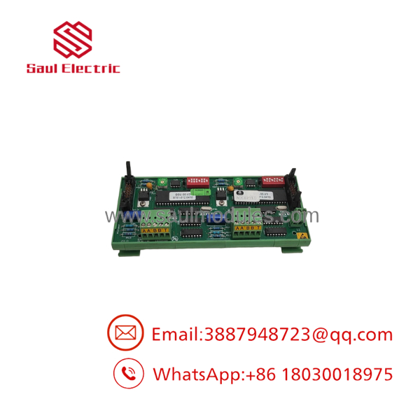
BSU-50-V3
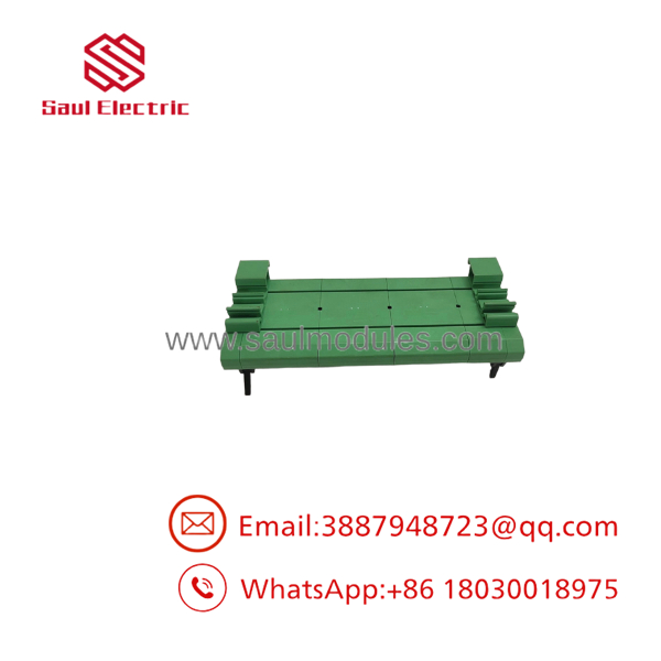
BSU-50-V3
The Veteran’s Tech Trap Guide (Crucial Value-Add)
⚠️ Match DIP Switches and Jumper Links Before Powering Up
The uses physical DIP switch blocks and jumper links to set port protocols (RS-232 vs RS-485), baud rates, and card addresses. Take a clear photo of the DIP switch settings on your old board before pulling it out. Setting these wrong will cause a total comm blackout or freeze the panel’s central processing unit.
❗ Watch Out for V1/V2 vs V3 Revision Differences
Do not attempt to replace a with an older BSU-50-V1 or V2 unless you verify baud rate compatibility. Older board spins used different optocoupler ICs and timing components that can cause intermittent checksum errors when linked with newer panel CPU software revisions. Stick to the V3 for maximum stability.
⚠️ Verify Shield Grounding on External Serial Lines
RS-485 lines running through a ship or industrial plant pick up heavy electrical interference. Ensure the cable shield is landed at one end only (usually at the main panel earth terminal). Landing shields on both ends creates a ground loop that will fry the driver ICs on your new card during high generator loads.
Frequently Asked Questions (FAQ for Conversion)
Q: Can I hot-swap the module while the main panel is powered on?
A: No. Removing or inserting this board while the internal 24V bus is active can arc the ribbon connector pins and damage the main CPU card. Always isolate power to the fire panel rack before swapping cards.
Q: How do I know if the comm port is working?
A: Check the onboard Tx and Rx LEDs next to the terminal headers. Under normal communication, both green/yellow LEDs should flash rapidly. If the Tx LED is flashing but Rx stays dark, the board is sending data but receiving no response from the remote device.
Q: Does the support direct Ethernet or Modbus TCP connections?
A: No. The is a legacy serial interface board (RS-232/RS-422/RS-485). To connect it to modern Ethernet networks or Modbus TCP controllers, you must pass its serial output through an external serial-to-ethernet converter module.
Q: Can I use this board to drive addressable fire detection loops?
A: No. The is strictly for panel-to-panel and system-level serial communications. Addressable field detectors require a dedicated loop driver card like the BSL-111A.
Q: What warranty coverage comes with your surplus or refurbished modules?
A: Every board we supply—whether new surplus or fully bench-tested refurbished stock—is backed by our full 12-month replacement warranty.

 Start Chat


