





Description
Product introduction and engineering value
Generator synchronization requires more than matching nominal voltage. The incoming machine must reach an acceptable frequency difference and phase relationship with the bus before the breaker closes. The BE3-25A coordinates this process by monitoring the electrical conditions and issuing correction commands to compatible governor and voltage-regulator circuits.
For maintenance teams supporting older generator installations, the unit may serve as a critical spare for an established synchronization scheme. The exact style determines which correction outputs and optional functions are available, making nameplate verification essential before procurement or commissioning.
Technical specifications
| Parameter | Documented details |
|---|---|
| Model | BE3-25A |
| Manufacturer part number shown in manual | 9 1661 00 100 |
| Device type | Automatic synchronizer |
| Primary application | Synchronizing an incoming generator with an energized bus or another generator |
| Frequency matching | Within ±0.1 Hz under the stated basic operating conditions |
| Phase-angle settings | ±5°, ±10°, ±15°, or ±20°, selected according to the unit’s configuration |
| Voltage-difference adjustment | Approximately ±5% to ±15% of bus voltage |
| Frequency correction | Output type depends on style; contact-based or compatible summing-point arrangements |
| Voltage matching | Optional; output configuration depends on style |
| Dead-bus closing | Optional; confirm the installed style code |
| Breaker control | Synchronizing output relay contacts |
| Front-panel indication | POWER and SYNC indicators; controls vary by style |
| Test facility | TEST/OPERATE switch on documented styles |
| Installation connections | Screw-terminal wiring; follow the specific manual diagrams |
| Product lifecycle | Discontinued by Basler Electric |
These are family-level specifications, not a confirmation of every feature on an unspecified BE3-25A unit. The manufacturer identifies the product as discontinued, and its manual explains that output functions vary by style.
Field applications and engineering context
Illustrative engineering scenario
Standby generator integration: A facility uses an older engine-generator set that must synchronize with an energized plant bus before the breaker can close. The BE3-25A monitors the incoming generator and bus conditions, provides frequency and phase-matching control, and enables the synchronizing output when the configured acceptance conditions are satisfied.
Other applications include:
- Industrial captive power plants: Synchronization of generator sets operating in parallel with a facility bus.
- Emergency power systems: Supporting generator synchronization in installations with legacy governor and voltage-regulator controls.
- Powerhouse retrofits: Maintaining an existing synchronization architecture while sourcing a discontinued spare, subject to a wiring and configuration review.
The BE3-25A is not simply a sync-check relay. Its auto-synchronizer functions can include correction outputs for governor and voltage-regulator control. Do not substitute a basic sync-check relay without confirming that the system does not depend on those correction functions.
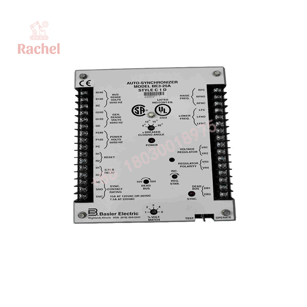
BE3-25A
QA and testing SOP
For a used, refurbished, or surplus BE3-25A, separate visual inspection from functional verification.
- Confirm the complete identification. Photograph the nameplate and record the full style designation, part number, and any revision markings.
- Inspect the hardware. Check the case, terminal blocks, switches, adjustment controls, indicators, and internal assemblies for damage or signs of unauthorized repair.
- Review the original configuration. Record the frequency-matching output type, voltage-matching option, dead-bus option, and relevant jumper settings before removing the existing unit.
- Verify the sensing inputs. Confirm generator and bus voltage connections, nominal ratings, phase relationships, and sensing-source arrangement against the applicable wiring diagram.
- Test correction outputs. Under controlled test conditions, verify that frequency and voltage correction outputs operate as required by the installed style.
- Test the synchronizing permissive. Use suitable test equipment to verify the configured frequency, phase-angle, and voltage acceptance conditions. Confirm that the breaker-close output does not operate outside the intended limits.
- Document the result. Record test conditions, measured values, output behavior, and any deviations before the unit is released for service.
Safety note: Generator synchronization testing involves potentially hazardous AC circuits and breaker-control circuits. Testing and commissioning should be performed by qualified power-system personnel using an approved procedure. Never test by allowing an uncontrolled out-of-phase breaker closure.
Veteran’s tech-trap guide
Trap 1: Ordering by alone
The style code identifies configuration options. Two units sharing the family designation may not have the same frequency-matching output, voltage-matching function, or dead-bus capability. Obtain a clear nameplate photo and compare the style chart before ordering.
Trap 2: Confusing synchronization with a breaker permissive
A sync-check relay generally determines whether electrical conditions are acceptable for closing. The can also generate correction commands to bring frequency and voltage toward their targets. A replacement that only provides a close permissive may leave the governor or regulator control loop incomplete.
Trap 3: Treating dead-bus closing as a universal feature
Dead-bus functionality is style-dependent. It also changes the logic used to authorize breaker closure. Confirm whether the original installation requires this option and validate the associated protection and interlock logic before energizing the replacement.
Frequently asked questions
Q1: What is the Basler used for?
It automatically synchronizes an incoming generator with an energized bus or another generator by monitoring frequency, phase angle, and voltage, then issuing correction signals and a synchronizing output when the configured conditions are met.
Q2: Is the still manufactured?
No. Basler Electric lists the as discontinued. Its product page points users toward the BE1-FLEX platform, but a successor should be selected only after reviewing the required functions and interface wiring.
Q3: Can a replace a BE3-25 sync-check relay?
Not automatically. The BE3-25 is a sync-check relay, while the is an auto-synchronizer with configurable correction outputs. Compare the complete control scheme, output contacts, sensing inputs, and required options before selecting a replacement.
Q4: Does every support dead-bus closing?
No. The dead-bus function is an option. Check the complete style code and the original wiring diagram rather than assuming it is present on every unit.
Q5: How should a surplus unit be authenticated?
Request photographs of the actual nameplate, confirmation of the full style designation, and a documented functional test. Unused surplus inventory is not automatically equivalent to current factory stock or proof of manufacturer-authorized distribution.
Q6: What warranty should buyers expect?
Warranty coverage depends on the supplier’s written terms and the unit’s condition. Confirm the warranty period, return window, DOA policy, and whether the test procedure covers the specific synchronization and correction functions needed at your site.


 Start Chat


