





Description
Key Technical Specifications
| Parameter | Value |
| Product Type | Proximitor / Seismic Monitor Module (Four-Channel) |
| Main Card Part Number | 176449-02 (Replaces legacy 140734-02) |
| Signal Inputs | 1 to 4 proximity, velocity, or acceleration transducer signals |
| Input Impedance | 10 kΩ (Standard I/O for Proximitor and acceleration inputs) |
| Power Consumption | 7.7 Watts (Typical) |
| Frequency Response | Direct and Gap: Within ±0.33% of full-scale (typical)
Vector Filter (1X & 2X): Valid for speeds of 60 to 100,000 cpm |
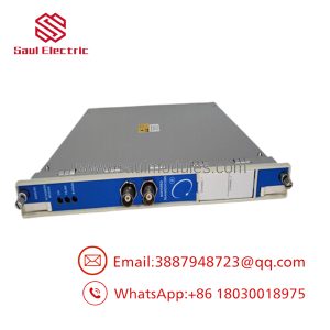
| LED Indicators | OK LED (Green), TX/RX LED (Green), Bypass LED (Red) |
| Analog Outputs | Individual 4-20 mA recorder values per channel (via associated I/O module) |
| Physical Dimensions | 244 mm x 24.4 mm x 242 mm (9.6″ x 0.96″ x 9.5″) |
| Product Net Weight | 0.82 kg (1.8 lbs) |
| Operating Temperature | -30 to +65 °C |
Product Introduction
The Bently Nevada 3500/42M (176449-02) is a high-performance, four-channel Proximitor / Seismic Monitor module that serves as a cornerstone for machinery protection inside the 3500 Series Rack. This module is engineered to continuously capture, condition, and analyze vibration and position measurements from rotating machinery, fully complying with API 670 standards.
The 176449-02 main processor is highly flexible; its four input channels can be programmed in pairs to execute different monitoring profiles simultaneously. For example, Channels 1 and 2 can monitor radial vibration via proximity probes, while Channels 3 and 4 process seismic signals from accelerometers or velocity sensors on the machine casing. By comparing real-time operational data against preconfigured Alert and Danger setpoints, the 3500/42M triggers protective relay outputs to shut down machinery before catastrophic physical failures occur.
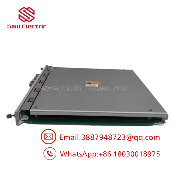
- 3500/42M 176449-02
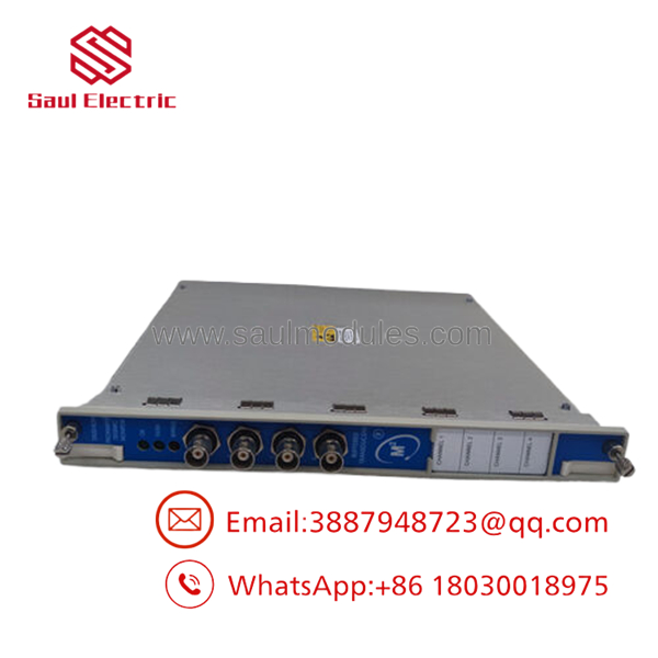
- 3500/42M 176449-02
Installation & Configuration Guide
Stage 1: Pre-Installation Preparation (Estimated Time: 15 minutes)
- ⚠️ Safety & Relay Warning: The 3500/42M is an active safety device. Replacing a functioning or partially failed monitor card can trigger a false machine trip if its relay paths are active. You must bypass all associated shutdown relays on the corresponding 3500/32 or 3500/33 relay cards, or coordinate with plant operations to place the targeted machinery loop into a safe manual bypass mode.
- Tools Required: Grounded ESD wrist strap, small flathead terminal screwdriver, laptop loaded with Bently Nevada 3500 Rack Configuration software, USB or Ethernet interface cable.
- Data Backup: Connect to the rack’s Transient Data Interface (TDI) module and upload the existing configuration file (
.3500format) to your laptop. This ensures you can instantly restore calibration and setpoint variables to the replacement module.
Stage 2: Removing the Old Module (Estimated Time: 5 minutes)
- Verify that the machinery has been isolated or that all associated alarm/trip relays are in bypass mode.
- Put on your grounded ESD wrist strap and attach the ground clip to the unpainted rack frame.
- Loosen the two captive retaining screws located on the front face of the 3500/42M module.
- Grasp the ejector tabs on the top and bottom of the card front plate, swing them outward to disengage the backplane connectors, and slide the card smoothly out of its slot.
Stage 3: Installing the New 176449-02 Module (Estimated Time: 10 minutes)
- Unpack the new 176449-02 module on an anti-static surface while wearing your ESD wrist strap.
- Inspect the rear pin arrays to ensure there are no bent or damaged connectors.
- Align the module card edge with the track guides inside the vacant rack slot.
- Slide the module back until the ejector levers touch the frame, then push the levers inward to seat the connectors firmly against the backplane.
- Tighten the front panel captive screws.
Self-Checklist:
- [ ] Module is fully flush with the front rack face
- [ ] Front panel screws hand-tightened to lock the card against vibration
- [ ] ESD wrist strap worn during the entire swap procedure
Stage 4: Power-On, Addressing, and Calibration (Estimated Time: 20 minutes)
- Once inserted, the module will auto-power from the rack’s active DC bus.
- Observe the front panel LEDs:
- OK LED: Flashing Green (indicates the card is booting or waiting for configuration).
- Bypass LED: Solid Red (indicates the channel alarms are bypassed, which is normal during new installation).
- Connect your configuration computer to the rack’s TDI interface port.
- Open the 3500 Rack Configuration software, write the stored
.3500configuration settings to the newly installed 3500/42M slot, and run a verification loop check on the proximity/seismic channels. - Once the live sensor gap voltages and vibration readings display correctly on your diagnostic software, clear the safety bypasses to return the module to active monitoring.
Frequently Asked Questions (FAQ)
What is the difference between the legacy 140734-02 and the 176449-02 module?
The 176449-02 is the modern, direct replacement upgrade for the legacy 140734-02 main card. Bently Nevada updated the internal processor architecture to improve component lifespan, signal filtering precision, and system reliability under sustained thermal stress. The 176449-02 slides into the same physical slot and interfaces seamlessly with existing rear I/O modules designed for the 140734-02.
Can I monitor proximity probes and casing velocity sensors with the same card?
Yes. The four channels on the 3500/42M are paired (Channels 1 & 2, and Channels 3 & 4). Each pair can be configured independently for different sensor inputs and measurement configurations. For example, you can set Channels 1 and 2 to process radial vibration from XY proximity probes, while dedicating Channels 3 and 4 to seismic velocity sensors measuring bearing housing casing vibration.
Why is the “Bypass” LED illuminated on the front panel?
The red Bypass LED indicates that one or more monitoring channels on the card have their alarm/trip functions temporarily deactivated. This occurs automatically when the card has not yet received a valid software configuration file, if the sensor signal goes out of bounds (triggering a “Not OK” state), or if a technician manually activates the “Rack Bypass” switch to perform maintenance.
Is the 3500/42M module hot-swappable?
Yes. The 3500 rack backplane is engineered to support active module replacement (hot-swapping) without powering down the entire rack. However, because inserting a new card can temporarily cause signal transitions on the backplane, it is essential to bypass all shutdown relays associated with the slot before swapping the card to prevent accidental machinery shutdown.
Why buy a surplus 176449-02 instead of ordering from the factory?
Critical turbomachinery cannot run safely without active vibration monitoring, making any downtime due to backordered parts extremely costly. Because Bently Nevada factory lead times can be substantial, we maintain an active stock of unused surplus and fully tested reconditioned 176449-02 modules to ship immediately, getting your machinery back online without delay.

 Start Chat


