





Description
Product Introduction
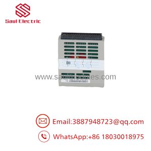
The Emerson Westinghouse 5X00121G01 is a specialized Fiber Optic Transceiver Module engineered for the Ovation Distributed Control System (DCS). It converts electrical controller bus signals into optical light pulses, extending sub-tier communication links across distant cabinet rows and remote plant facilities without signal degradation.
Built to operate in severe electro-magnetic environments, the 5X00121G01 provides total galvanic isolation between connected racks. By replacing long copper wire runs with fiber optic media, it eliminates ground potential differences and heavy electrical noise interference caused by high-voltage switchgear, variable frequency drives, and atmospheric lightning surges.
Key Technical Specifications
| Parameter | Value |
| Module Type | Ovation Fiber Optic Transceiver / Media Converter |
| Part Number | 5X00121G01 |
| Manufacturer | Westinghouse / Emerson Process Management |
| System Compatibility | Emerson Ovation DCS / WDPF Architecture |
| Optical Connector Type | ST standard bayonet connectors |
| Fiber Media Type | Multi-mode fiber optic cable (62.5/125 µm or 50/125 µm) |
| Wavelength | 850 nm / 1300 nm nominal optical band |
| Isolation Type | Complete optical / galvanic separation |
| Power Input | 24V DC supplied via Ovation Baseplate |
| Mounting Format | Single-slot Ovation I/O Baseplate / Extension slot |
Application Scenarios & The “Trench” Experience
Picture this: It’s 2:30 AM during a heavy thunderstorm, and a combined-cycle plant’s cooling tower fan subsystem drops offline. The main control room displays flash a “Remote Sub-Tier Bus Offline” alarm. The issue isn’t a dead controller or blown field fuse—a ground potential spike caused by a nearby lightning strike jumped into a long copper communication cable, cooking the electrical transceivers on both ends of the run.
In our field experience, converting long copper inter-cabinet trunks to fiber using modules like the 5X00121G01 is the single best way to permanently stop noise-induced communication drops. Primary application scenarios include:
- Power Generation – Switchyard & Substation I/O Links: Connects central control rooms to remote I/O enclosures located inside high-voltage transformer yards without ground loop risks.
- Petrochemical Refineries – Tank Farm Telemetry: Transmits high-speed process data across long distances into intrinsically safe enclosures via spark-free fiber cabling.
- Water & Utilities – Remote Treatment Basins: Extends Ovation sub-tier highways across hundreds of meters between intake pumps and main processing buildings.
- Heavy Manufacturing – High-EMI Steel Mills: Operates flawlessly alongside massive electric arc furnaces and high-power VFD lineups.
Field Case Study: A chemical processing facility in Texas suffered intermittent bus timeouts whenever a 4160V boiler feed pump motor started up. High electromagnetic interference was coupling directly onto their copper sub-tier bus expansion cables. We bench-tested the optical transmit power and receiver sensitivity on a surplus 5X00121G01 module, shipped it out overnight, and assisted the site team in converting the sub-tier link to multi-mode fiber. The complete optical isolation instantly solved the interference issue, eliminating all communication alarms.
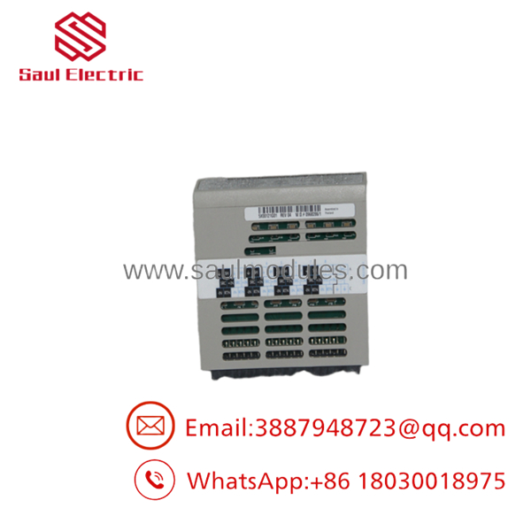
5X00121G01
Transparency SOP: Quality Assurance & Testing
We do not just ship surplus boxes; we physically test every module on actual Emerson Ovation hardware using specialized optical tools. Our 5-step SOP includes:
- Inbound Visual & Optical Inspection: Check PCB components for thermal darkening, inspect backplane edge pins, and examine ST fiber ports under magnification for dust or scratched ferrule optics.
- Backplane Interface & Power Test: Slot the card into an active Ovation baseplate to verify backplane bus handshakes and power rail health.
- Optical Power & Link Budget Test: Measure LED/laser output power (in dBm) using calibrated optical power meters and run loopback communication tests across attenuated fiber lines.
- Thermal Stress Chamber Run: Operate the module under continuous transmit/receive cycles in an elevated-temperature chamber to detect heat-induced laser diode attenuation.
- Cleanroom Care & ESD Packaging: Clean optical ports with lint-free swabs, attach dust caps to all ST ports, and seal the cleared board in anti-static shielding bags with custom foam padding.
The Veteran’s Tech Trap Guide (Crucial Value-Add)
- ⚠️ Clean Optical Ferrules Before Connection: Never connect a fiber patch cable into a 5X00121G01 port without cleaning the cable ferrule first. A single microscopic speck of dust inside the ST receptacle can scratch the internal lens or block enough light to cause random, high-bit-error packet drops.
- ❗ Verify Tx and Rx Cable Cross-Over: Always double-check that the Transmit (Tx) port on the local 5X00121G01 connects to the Receive (Rx) port on the remote transceiver card. Swapping Tx and Rx lines is the most common reason a replacement fiber module appears dead upon initial installation.
- ⚠️ Mind Fiber Cable Minimum Bend Radius: Avoid tightening zip-ties down on fiber patch cords or routing them around sharp cabinet sheet metal edges. Over-bending multi-mode fiber causes micro-bends that scatter the optical signal below the receiver’s minimum decibel threshold.
- ❗ Inspect Baseplate Backplane Pins: Ovation baseplate backplanes are unforgiving. Grab a flashlight and check inside the slot before seating the card. Inserting the board at an angle can flatten the rear pins and short out the 24V supply rail.
Frequently Asked Questions (FAQ for Conversion)
Q: Is the 5X00121G01 module hot-swappable while the Ovation rack is powered?
A: Mechanically, the Ovation baseplate supports hot insertion. Practically, pulling an active fiber transceiver will sever the communication link to all downstream remote I/O baseplates on that fiber loop. Always place affected control loops into manual bypass before pulling the module.
Q: What type of fiber optic cable is required for the 5X00121G01?
A: This board is engineered for standard multi-mode optical fiber (typically 62.5/125 µm or 50/125 µm core/cladding) terminated with standard bayonet ST-style connectors.
Q: What is the most common point of failure on these optical modules?
A: Optical transmitter LED/laser diode degradation over years of continuous exposure to elevated cabinet heat, or contaminated optical ports caused by missing dust caps in dirty control rooms.
Q: Why choose test-certified surplus over ordering direct from the OEM?
A: Factory lead times for legacy Ovation fiber interface boards often stretch out for months. Our surplus modules are bench-tested with optical power meters, ready to ship today, and priced significantly lower without risking plant uptime.
Q: What warranty coverage comes with this module?
A: We back the 5X00121G01 with a full 12-month replacement warranty. If a module fails during bench testing or field operation, we swap it immediately from our ready stock.

 Start Chat


