





Description
Key Technical Specifications
| Parameter | Value |
| Network Standard | IEEE 802.3 10BASE-T Ethernet |
| Data Transfer Rate | 10 Mbps (Half-Duplex standard operation) |
| Physical Interface | 1 x RJ45 Female Connector |
| Host Connectivity | Direct mating connector for D20/D200 main processor modules |
| Cabling Requirement | Category 3, 4, or 5 UTP (Unshielded Twisted Pair), maximum 100 meters |
| Diagnostic LEDs | Link Status, Transmit (TX), Receive (RX), Power |
| Power Supply | Derived entirely from the host D20 processor board interface |
| Operating Temperature | −40 to +70 °C (−40 to +158 °F) substation-hardened configuration |
Product Introduction
The GE Harris D20 MIC (Media Interface Card) 10BASE-T is a specialized networking daughtercard designed for legacy D20 and D200 Substation Automation RTUs (Remote Terminal Units). This component mounts directly onto the master processor board, acting as the physical and electrical translation layer that bridges the RTU’s processing core to an external 10 Mbps Ethernet LAN.
SCADA engineers rely on the 10BASE-T MIC to modernize legacy power distribution substations. Instead of routing telemetry over low-speed serial links, this module enables the D20 to communicate natively via TCP/IP protocols like DNP3 over IP or IEC 60870-5-104. Its design conforms to strict substation electromagnetic interference (EMI) guidelines, ensuring reliable link stability during high-voltage switching events.
Installation & Configuration Guide
Stage 1: Pre-Installation Preparation (Estimated Time: 15 minutes)
- ⚠️ Safety First: The D20 RTU collects critical data from high-voltage substation lines. Replacing components while energized risks shorting data buses, disrupting utility telemetry, and causing safety hazards. De-energize the D20 chassis power supply and verify with a multimeter that all backplane power rails read 0 V. Lock out and tag out the supply circuit.
- Tools Required: Grounded static-dissipative ESD wrist strap, small non-magnetic Phillips screwdriver, anti-static cleaning wipe, ConfigPro software workstation.
- Data Backup: Connect your engineering laptop to the RTU prior to shutdown. Save a master backup copy of the current D20 device profile, including IP assignments, node routing maps, and subnet masking indexes.
Stage 2: Removing the Old Module (Estimated Time: 10 minutes)
- Attach your ESD grounding wrist strap to the bare structural steel framework of the RTU cabinet.
- Unplug the existing RJ45 network patch cable from the MIC faceplate block. Label the cable to prevent cross-patching later.
- Loosen the retaining faceplate hardware or extract the main D20 processor module housing from the rack frame to gain access to the physical circuit board layer.
- Locate the MIC daughtercard plugged into the header pins of the host board.
- Gently pull the old MIC straight upward from its mounting standoffs to protect the fine connector pins underneath. Do not rock or twist the board during removal.
Stage 3: Installing the New Module (Estimated Time: 15 minutes)
- Keep your ESD wrist strap secured. Remove the new 10BASE-T MIC from its static shielding wrap.
- Inspect the array of pins on the underside of the new card to ensure they are straight and aligned.
- Align the card’s mating sockets with the male header pins on the host D20 processor board. Align the board holes with the physical support standoffs.
- Apply even, downward pressure on the card edges until the connectors seat firmly. Secure the assembly using the non-magnetic hardware.
- Re-insert the primary processor assembly into the D20 chassis housing and lock the faceplate down. Reattach your RJ45 network cable.
- Self-Checklist:
- [ ] Daughtercard seated completely flush against the host board socket.
- [ ] Standoff support hardware tightened down securely.
- [ ] RJ45 patch cable click-locked into the communication port interface.
Stage 4: Power-On & Testing (Estimated Time: 20 minutes)
- Re-energize the D20 chassis power distribution rails.
- Watch the indicator LEDs on the new MIC faceplate. The POWER indicator should glow solid, and the LINK LED should illuminate once it negotiates a physical path with the network switch port.
- Execute a persistent ping from your SCADA workstation to the fixed IP address assigned to the D20 node.
- Open the ConfigPro diagnostic software terminal. Check the network statistic log to verify that data packets are routing correctly with zero framing errors or packet collisions.
- ⚠️ Troubleshooting Note: If the LINK LED stays off, check that the network switch port is configured for automatic negotiation or fixed at 10 Mbps Half-Duplex. Modern managed switches set to fixed 100/1000 Mbps speeds cannot communicate with a legacy 10BASE-T interface.
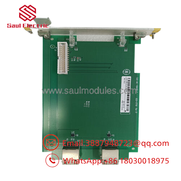
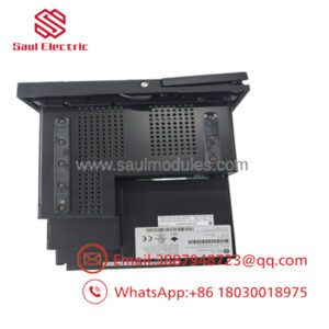
- D20 MIC 10BASE-T
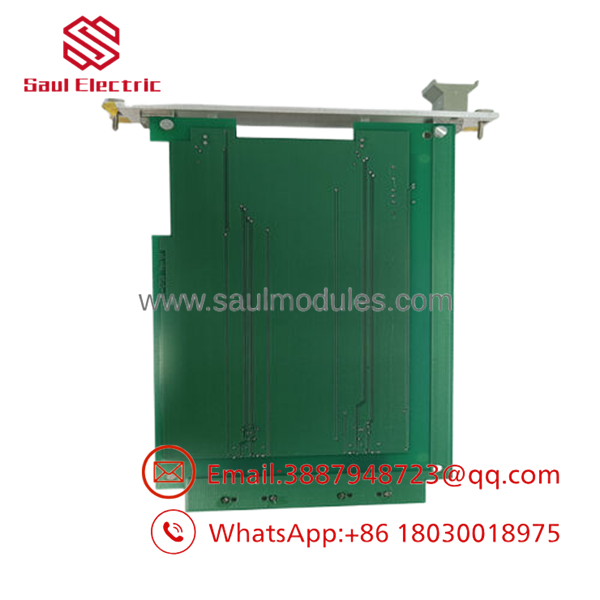
- D20 MIC 10BASE-T
Frequently Asked Questions (FAQ)
Can I upgrade my D20 RTU to a faster network speed by simply swapping this card for a 100BASE-TX card?
No, you cannot swap just this card for a higher-speed version. The overall data bus layout and execution clock rate of the legacy D20 processor board are matched to the 10 Mbps processing threshold of this 10BASE-T MIC. If your substation project requires 100 Mbps or 1 Gbps fiber infrastructure connectivity, you must update the entire processing assembly to a newer generation platform, such as the D200 or D30 advanced automation controller.
Does this MIC contain an onboard memory block that stores the RTU’s IP address?
No, the 10BASE-T MIC functions purely as a physical media interface adapter (similar to a transceiver). It does not hold site data, flash configurations, or operational code parameters. The IP addresses, subnet routing tables, and communications configurations are stored inside the flash memory chip on the parent D20 processor board. Replacing a failed MIC will not erase your configuration data.
Why is my new 10BASE-T MIC failing to communicate with a brand-new network switch?
Modern Gigabit and managed Ethernet switches often disable legacy 10 Mbps communication paths by default on their port profiles, or their auto-negotiation protocol fails to recognize old half-duplex hardware. To fix this, log into the managed network switch configuration panel and manually force the target port profile to 10 Mbps / Half-Duplex, rather than leaving it on Auto-Negotiate.
Is it safe to unplug the RJ45 network patch cable while the RTU is operating under load?
Yes, you can disconnect the RJ45 Ethernet patch cable while the unit is running without damaging the hardware components. However, doing so will cause an immediate loss of communication between the substation and your master SCADA control room. This will log telemetry link drop alarms and blind operators to live breaker positions. Ensure your control room is notified before disconnecting the cable.
Why does this board use an older connection instead of fiber optics?
This specific MIC variant was engineered to connect to copper-shielded twisted-pair station networks inside an automation panel. If your substation layout dictates an optical fiber run to prevent ground loop problems or high-voltage EMI interference, you must either couple this 10BASE-T card to an external copper-to-fiber media converter or use a fiber-specific variant of the D20 MIC assembly.


 Start Chat


