





Description
Key Technical Specifications
| Parameter | Value |
|---|---|
| Manufacturer | GE |
| Model | DS200DCFBG1BLC |
| Product Type | DC Feedback Power Supply Board (DCFB) |
| Product Series | Mark V Speedtronic |
| Manual Reference | GEI-100028 |
| Input Voltage | 38–115 VAC (24 VDC control input supported in system configuration) |
| Supported Frequency | Up to 500 kHz (application dependent) |
| Control Power Outputs | +5 VDC, +15 VDC, -15 VDC, +24 VDC |
| Integrated Circuits | AC monitoring, DC monitoring, motor field power, driver power circuits |
| Configuration | 12 jumpers and 7 DIP switches |
| Protection | 3 onboard fuses |
| Diagnostics | 2 LEDs, 1 neon indicator, 5 onboard test points |
| Connectors | 18 plug connectors and 9 stab connectors |
| Compatible Systems | GE Mark V, AC2000, DC2000, CB2000, FC2000, ME2000, EX2000 drive platforms |
These specifications are based on the GEI-100028 board documentation and published Mark V hardware references.
Product Introduction & Supply Chain Strategy
The GE DS200DCFBG1BLC is a DC Feedback Power Supply Board (DCFB) designed for the GE Mark V Speedtronic turbine control platform. It supplies regulated low-voltage control power for the controller, provides motor field power, powers enclosure cooling fans, and conditions voltage feedback signals for transmission to the SDCC/LDCC control processor. Voltage feedback is converted into frequency signals through onboard circuitry, enabling precise regulation of excitation and drive performance.
The board is compatible with numerous GE industrial drive families including AC2000, DC2000, CB2000, FC2000, ME2000, and EX2000, making it one of the most widely deployed Mark V power boards. Since the Mark V platform has reached the mature stage of its lifecycle, maintaining New Surplus inventory reduces Total Cost of Ownership (TCO), minimizes procurement lead times, and lowers operational risk compared with refurbished electronics. Facilities operating critical turbines should maintain 1–2 spare DCFB boards and evaluate last-time-buy opportunities.
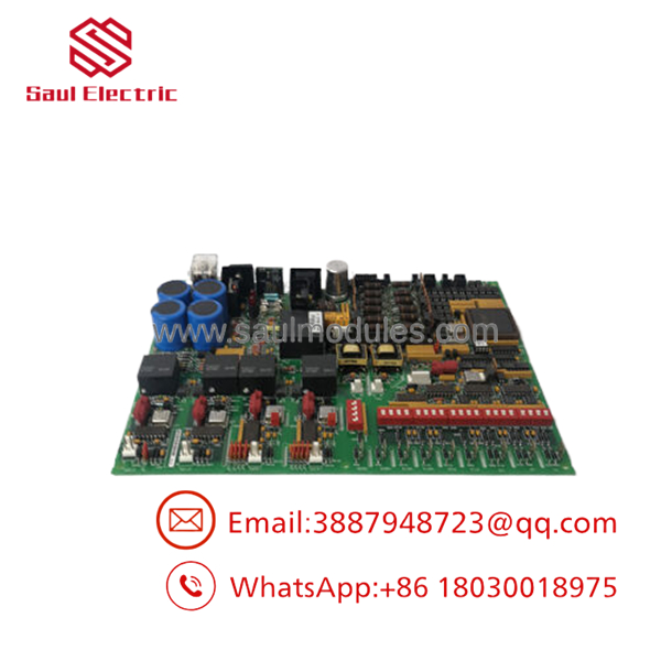
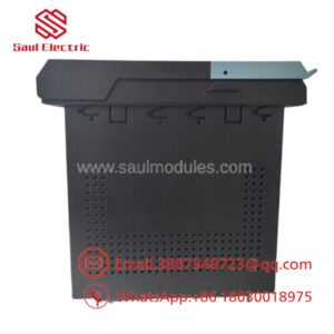
- DS200DCFBG1BLC
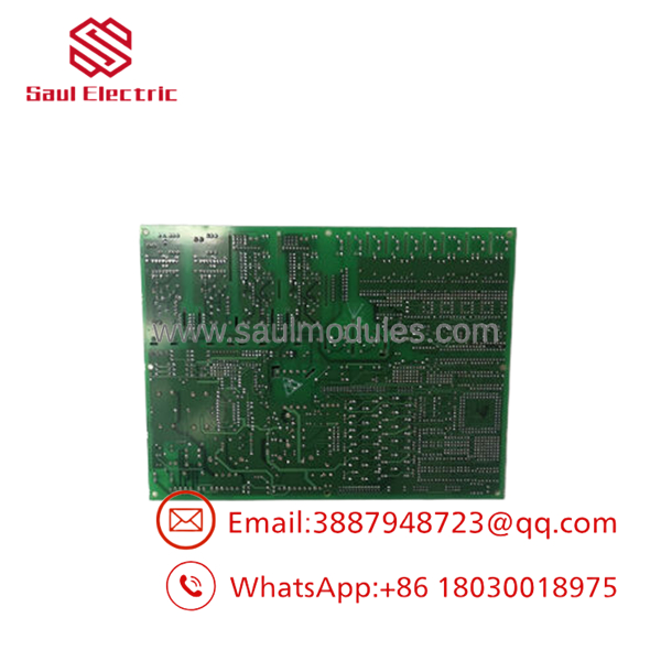
- DS200DCFBG1BLC
Installation & Configuration Guide
Stage 1 – Preparation
- Perform Lock-Out/Tag-Out (LOTO).
- Remove AC control power.
- Wear an approved ESD wrist strap.
- Record all jumper and DIP switch settings.
- Photograph every connector before removal.
Stage 2 – Removal
- Verify all control voltages are absent.
- Disconnect plug and stab connectors.
- Remove mounting hardware.
- Carefully extract the board.
- Inspect connectors and fuse holders for damage.
Stage 3 – Installation
- Verify the replacement is DS200DCFBG1BLC.
- Install the board into the original location.
- Match all jumper and DIP switch configurations.
- Reconnect all wiring according to the original layout.
- Verify fuse ratings before energizing.
Stage 4 – Commissioning
- Restore AC control power.
- Verify onboard LED status indicators.
- Measure +5 VDC, ±15 VDC, and +24 VDC at the designated test points.
- Confirm proper communication with the SDCC/LDCC controller.
- Perform complete turbine control functional testing before returning the unit to operation.
Firmware / Software Versions & Upgrade Notes
- The DS200DCFBG1BLC is primarily a hardware power board and does not require firmware updates.
- Verify compatibility with the installed Mark V control processor revision.
- Preserve all jumper and DIP switch settings when replacing the board.
- Inspect and replace protective fuses if required before commissioning.
- After installation, verify all regulated power rails and diagnostic indicators using the onboard test points described in GEI-100028.
Frequently Asked Questions (FAQ)
Q1. Is this a New Original product?
Yes. It is typically supplied as New Original / New Surplus. The board is unused, not repaired, and should undergo serial number verification, visual inspection, and functional testing before shipment.
Q2. What is the primary function of the ?
It generates regulated control voltages, powers the motor field and enclosure fan, monitors AC/DC power, and conditions feedback signals for the Mark V turbine control system.
Q3. Which systems are compatible with this board?
The board is compatible with GE Mark V Speedtronic systems and numerous GE industrial drive platforms, including AC2000, DC2000, CB2000, FC2000, ME2000, and EX2000.
Q4. What diagnostic features are included?
The board includes 2 LEDs, 1 neon indicator, 5 voltage test points, 3 protective fuses, 12 configuration jumpers, and 7 DIP switches to support maintenance and troubleshooting.
Q5. Can the board be replaced while energized?
No. The board should only be replaced after isolating all control power sources and following GE-approved maintenance procedures to prevent equipment damage and personnel hazards.
Q6. What warranty is typically offered?
Professional industrial automation suppliers generally provide a 12 month warranty, together with electrical testing, serial number verification, anti-static packaging, and export-grade shipping.
Q7. What inventory strategy is recommended?
For facilities operating GE Mark V Speedtronic turbine control systems, maintain 1–2 New Surplus boards as critical spare inventory. Since OEM production has largely ended, proactive lifecycle management, qualified supplier consolidation, and last-time-buy planning are recommended to ensure long-term system support.


 Start Chat


