





Description
Key Technical Specifications
| Parameter | Value |
| Functional Acronym | AEBI (Analog Excitation Bridge Interface) |
| Input Operating Voltage | 24 V DC nominal |
| Typical Power Draw | 5 W |
| Isolation Voltage | 1500 V RMS galvanic isolation |
| Signal Compatibility | Analog bridge inputs via shunt resistors / transformers |
| Interrogation Interface | 15-pin D-sub for communication link pathways |
| Power Supply Interface | 10-pin local header pinout |
| PCB Composition | FR-4 material, 1.6 mm board density layer |
| Operating Temperature | −40 to +70 °C (−40 to 158 °F) |
| Storage Temperature | −40 to +85 °C (−40 to 185 °F) |
| Relative Physical Mass | 0.32 kg (0.71 lbs) |
| Physical Dimensions | 29.2 cm × 13.0 cm × 2.7 cm |
Product Introduction
The GE IS210AEBIH1BED is an Analog Excitation Bridge Interface (AEBI) circuit board assembly manufactured for General Electric’s legacy Speedtronic Mark VI and newer Mark VIe turbine control networks. This dedicated hardware component serves as a signal interface for turbine generator excitation systems, translating physical parameters from the excitation bridge into stable processing data for upstream controllers.
Engineered to operate reliably within power generation and large mechanical drive deployments, the IS210AEBIH1BED conditions voltage and current signals measured across shunt resistors or transformers. Its integrated multi-stage filtering and 1500 V RMS galvanic isolation circuit shield the core 32-bit control layer from destructive transient surges and common-mode electrical noise inherent to generator excitation decks.
Installation & Configuration Guide
Stage 1: Pre-Installation Preparation (Estimated Time: 20 minutes)
- ⚠️ Safety First: Notify operations before pulling this board. Isolate the turbine generator’s active excitation loop and verify that the system is entirely de-energized. High residual voltages exist around excitation bridge networks; verify safe states with a multimeter before touching terminal paths.
- Tools Required: Grounded static-dissipative wrist strap, anti-static safety pad, Philips PH2 driver, and a calibrated digital multimeter.
- Data Backup: Document the physical slot position and hardware layout of the existing card. Use your engineering terminal to verify that active diagnostic alarm tables are documented for subsequent comparison.
Stage 2: Removing the Old Board (Estimated Time: 5 minutes)
- Clamp your ESD strap to a verified bare-metal ground terminal on the enclosure chassis frame.
- Carefully disconnect the 15-pin D-sub communication bridge link and the 10-pin local power line headers.
- Back out the retaining screws positioned along the top and bottom edge tracks of the board’s chassis guides.
- Pull the board straight forward out of its mounting tray to prevent bending backplane pins or scratching internal circuits. Place it inside a protective ESD bag immediately.
Stage 3: Installing the New Board (Estimated Time: 10 minutes)
- Unpack the new IS210AEBIH1BED board on your grounded anti-static pad.
- Configuration Clone: Verify that all onboard jumper nodes, hardwired configuration traces, and revision stamps (Group H1, Revision ED) match the original card layout exactly.
- Slide the board smoothly along the alignment tracks into the target housing enclosure until it seats flush.
- Tighten the retaining screws along the face track to secure physical grounding continuity.
- Reattach the 10-pin power line link and secure the 15-pin D-sub communication connector pins.
Stage 4: Power-On & Testing (Estimated Time: 15 minutes)
- Verify that incoming power rails measure a steady 24 V DC using your multimeter.
- Energize the local rack or excitation interface bay.
- Watch the local LED status indicators. The primary green operational indicator should settle into a stable state, indicating that initialization cleared safely.
- Open your configuration tool to confirm that data transmission packets are updating through the interface bus without register errors.
- ⚠️ Troubleshooting Note: If the control system throws a communication sync or hardware identification mismatch fault, verify that your engineering platform’s system configuration profile recognizes the specific “ED” revision suffix.
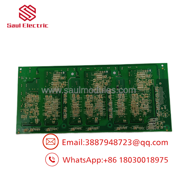
- IS210AEBIH1BED
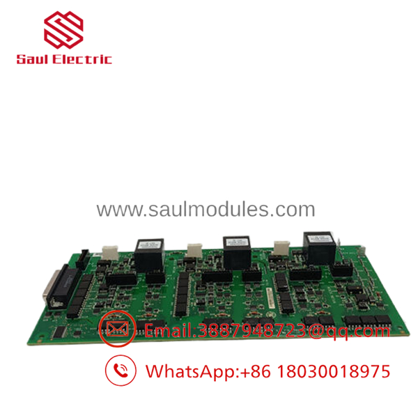
- IS210AEBIH1BED
Frequently Asked Questions (FAQ)
What specific role does the “AEBI” acronym point to in my control system?
AEBI stands for Analog Excitation Bridge Interface. This board functions as the physical and electrical translation layer for turbine generator excitation systems. It filters and conditions high-voltage/high-current analog signals down into precise, isolated digital data streams that the primary Mark VI/VIe processing core uses to calculate real-time voltage regulation.
Can this board be replaced while the turbine generator is turning or online?
Absolutely not. The IS210AEBIH1BED directly handles excitation bridge monitoring. Pulling this module while the system is live will immediately disrupt the generator’s voltage regulation feedback loop, inducing an instantaneous turbine trip or triggering a major electrical fault on the generator deck.
What is the practical difference between the baseline IS210AEBIH1B and this ED model?
The part number tracks specific factory hardware revision rollouts. The base acronym layer (AEBI), group assembly configuration (H1), and physical footprint match the original series, but the “ED” suffix denotes a later-stage component revision. These revisions typically fix component obsolescence issues or improve signal filtering characteristics on the PCB layers.
Why is original technical documentation for the IS210 series difficult to find online?
GE manages Speedtronic system components as proprietary industrial system hardware, meaning full internal layout sheets are typically bundled inside complex proprietary manuals (such as GEH-6721 for Mark VIe). This makes standalone datasheets rare. Field engineers rely on physical board matching, jumper cross-referencing, and terminal interface checks during replacement routines.
Are these surplus items checked for reliability before shipment?
Yes. Every piece of surplus stock we distribute undergoes structural inspections, trace verification, and bench validation routines to ensure functional capability. Because these legacy series are no longer manufactured directly by the OEM, we provide an independent 1-year operational warranty covering all components, ensuring reliable drop-in replacement performance out of the box.



 Start Chat


