





Description
Product Introduction
The GE DS200DDTBG1A is an LCI Auxiliary I/O Terminal Board used in the GE LS2100 Static Starter Control System. It serves as the interface between external field wiring and the control electronics, providing signal conditioning, isolation, and termination for analog and digital auxiliary signals. The board connects directly to the IS200ADMAH1A analog interface board through high-density connectors.
Unlike a simple terminal strip, the DS200DDTBG1A actively conditions incoming signals before passing them to the control processor. It supports high-voltage AC inputs, CT and Hall-effect current inputs, voltage inputs, and 4–20 mA current loops while providing buffered analog outputs for external equipment. This makes it an important interface board within the LS2100 LCI architecture.
Key Technical Specifications
| Parameter | Value |
|---|---|
| Manufacturer | General Electric |
| Model | DS200DDTBG1A |
| Product Family | LS2100 Static Starter |
| Product Type | Auxiliary I/O Terminal Board |
| Functional Acronym | DDTB |
| Compatible Board | IS200ADMAH1A |
| Analog Outputs | 4 Buffered ±10 V Outputs |
| Current Loop Support | 4–20 mA Inputs |
| LEDs | 17 Status/Diagnostic LEDs |
| Jumpers | 12 Three-pin Jumpers |
| Test Points | 33 |
| Identification | Electronic ID Memory (1-Wire LAN) |
| Installation | Internal Control Cabinet PCB |
| Product Status | Legacy / Discontinued |
Application Scenarios & The “Trench” Experience
Here’s a situation that’s familiar in power plants.
A gas turbine refuses to accelerate during startup. The firing sequence is normal. The LCI power bridge passes every electrical check. Operators suspect the DSP controller, but diagnostics eventually reveal that auxiliary analog signals never reach the processor because the terminal board has failed after years of vibration and thermal cycling.
Typical applications include:
- Power Generation — LCI static starter systems for large synchronous generators where auxiliary analog and digital signals must be conditioned before reaching the DSP.
- Combined Cycle Plants — Gas turbine starting systems requiring CT, Hall-effect, and analog signal interfaces.
- Industrial Utilities — High-power synchronous motor starting applications using LS2100 control cabinets.
- Petrochemical Plants — Compressor and pump starting systems where multiple auxiliary feedback signals are monitored.
- Mining Operations — Large mill motor starting systems using GE LCI technology.
Field Replacement Example
During commissioning after a turbine overhaul, operators observed unstable analog feedback during the acceleration sequence. Inspection found oxidation on the DDTB terminal board combined with a damaged input channel. After replacing the DS200DDTBG1A, verifying jumper positions, and confirming analog scaling, the LCI completed a successful start without further alarms.
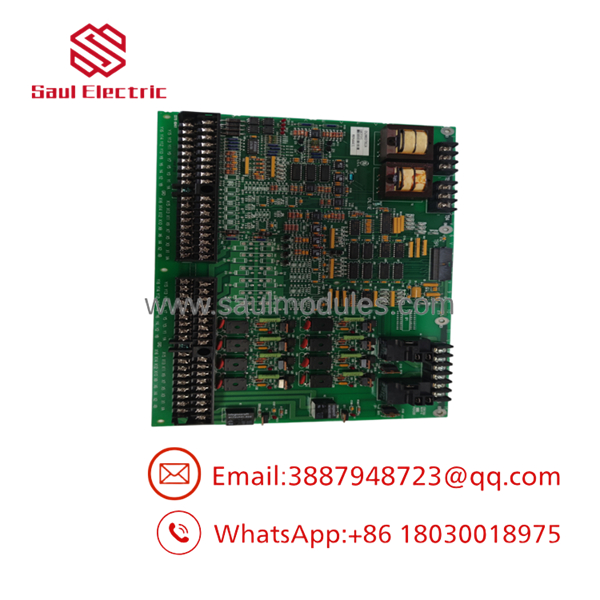
- DS200DDTBG1A
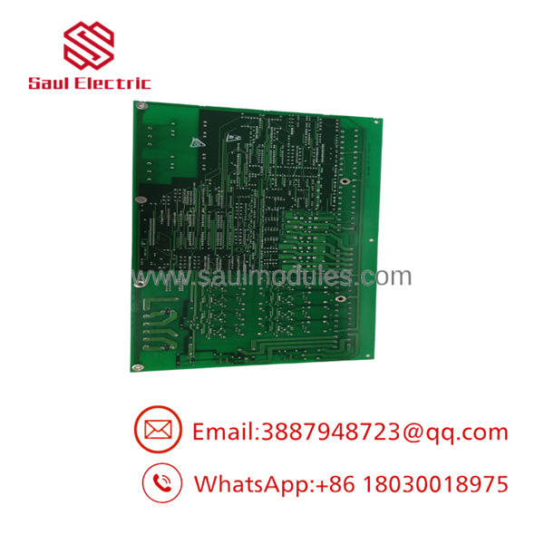
- DS200DDTBG1A
Transparency SOP: Quality Assurance & Testing
We don’t just ship boxes; we test them on compatible GE LS2100 hardware whenever practical.
- Inbound Inspection
- Verify complete catalog number and PCB revision.
- Inspect connectors, screw terminals, jumpers, and LEDs.
- Check for corrosion, overheating, and unauthorized repair.
- Live Functional Testing
- Install on a compatible LS2100 test platform.
- Verify communication with the attached ADMA board.
- Confirm LED operation and board identification.
- Electrical Parameter Checks
- Test buffered analog outputs.
- Verify current-loop inputs.
- Check terminal continuity and isolation.
- Hardware Verification
- Record board revision.
- Verify electronic ID memory.
- Confirm compatibility with customer requirements.
- Final QC & Anti-static Packaging
- Complete operational inspection.
- ESD-safe packaging.
- Shock-resistant shipping materials.
- Full serial-number traceability.
The Veteran’s Tech Trap Guide
⚠️ Don’t overlook the jumper configuration.
The twelve jumpers determine whether several input channels operate as CT/LEM inputs or 4–20 mA current-loop inputs. Installing the replacement with the wrong jumper settings can produce misleading measurements without generating an obvious fault.
❗ Inspect the ADMA board before replacing the DDTB.
The depends on the IS200ADMAH1A for power and communication. If the ADMA board has failed, replacing only the terminal board will not restore system operation.
⚠️ Verify analog output scaling.
The board provides ±10 V buffered analog outputs derived from the ADMA board. Confirm output scaling during commissioning before reconnecting external control equipment.
❗ Use the test points.
The board includes 33 dedicated test points. Before removing it, compare input and output signals against the maintenance manual. Many apparent board failures are actually field wiring or sensor issues.
Frequently Asked Questions (FAQ)
Q1. What is the primary function of the ?
It serves as the auxiliary input/output terminal board for the GE Load Commutated Inverter system, conditioning and routing analog and digital field signals to the control processor.
Q2. Which board does the connect to?
It interfaces directly with the IS200ADMAH1A Analog Interface Board, which supplies both power and communication.
Q3. How many analog outputs are available?
The board provides four buffered analog outputs with a nominal ±10 V output range for external connections.
Q4. What diagnostic features are built into the board?
The board includes 17 LEDs, 33 test points, onboard electronic identification memory, and configurable jumpers for multiple input types, simplifying maintenance and troubleshooting.
Q5. Can this board be replaced without changing controller software?
Yes. If the replacement is the same hardware revision and jumper configuration, no application software changes are normally required. After installation, verify I/O scaling, signal integrity, and system diagnostics before returning the equipment to service.
Q6. Why do these boards usually fail?
The most common causes are prolonged thermal exposure, vibration, oxidized connectors, surge events on field wiring, and aging electronic components. Actual PCB failures are less common than wiring or connector problems.
Q7. What warranty is typically provided?
Most industrial automation suppliers offer a 12-month warranty on functionally tested new surplus or professionally refurbished boards. Before commissioning, verify the board revision, jumper positions, analog scaling, and compatibility with the connected IS200ADMAH1A and the control cabinet.


 Start Chat


