





Description
Key Technical Specifications
| Parameter | Value |
| Network Interface Speed | 2.125 Gb/s serial data rate |
| Port Configuration | Up to 8 Small Form-Factor Pluggable (SFP) optical transceivers |
| Supported Fiber Types | Multimode (short distance) or Single-mode (up to 10 km loop) |
| Network Scalability | Cascade support up to 32 hubs for a maximum of 256 nodes |
| Local Management Interface | 1 x RS-232 serial port via 9-pin female D-sub connector |
| Remote Management Interface | 1 x 10Base-T Ethernet TCP/IP port via RJ45 layout |
| Fault Tolerance Mechanism | Automatic independent port bypass upon loss of signal (LOS) or sync pattern |
| Power Requirements | Universal 90 to 264 V AC, 47 to 440 Hz line frequency, 25 W max draw |
| Fuse Specification | 1 A, 250 V, 5 x 20 mm fast-acting glass fuse (IEC 60127-2) |
| Form Factor Dimensions | Standard 19-inch 1U rack mount layout or desktop configuration |
| Operating Temperature | 0 to +65 °C (32 to 149 °F) environment rating |
| Mean Time Between Failures | 431,524 hours (calculated MTBF performance metrics) |
Product Introduction
The GE ACC-5595-208 is an industrial managed 8-port fiber-optic hub optimized to distribute deterministic, deterministic real-time data across high-speed nodes. Engineered to manage networks using the VMIVME-5565 or PCI-5565 product families, this hub provides an active transmission path with an operational throughput of 2 Gb/s, maintaining low-latency memory synchronization between distributed physical computing hosts.
Unlike conventional commercial network switches that rely on store-and-forward architectures, this assembly regenerates serial optical signals at each port, eliminating link attenuation, jitter, and signal insertion losses. Plant networks deploy this hardware in safety-critical applications—including flight simulators, turbine control rings, and high-frequency production lines—where communication latency gaps cannot exceed sub-millisecond ranges.
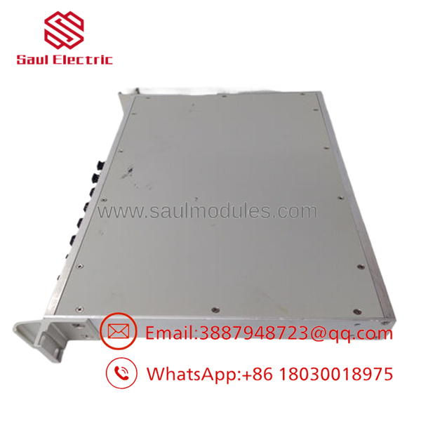
- VMIACC-5595-208
Installation & Configuration Guide
Stage 1: Pre-Installation Preparation (Estimated Time: 20 minutes)
- ⚠️ Safety First: Lock out and tag out the main AC distribution line feeding the network rack area. Verify that any cascading loops mapped to alternative machinery are placed in a safe local maintenance mode to avoid emergency stop triggers.
- Tools Required: Grounded anti-static ESD wrist strap, optical fiber cleaning clickers (LC-type), cross-tip screwdriver, and an RJ45 patch cable connected to a terminal PC.
- Data Backup: Document the IP assignments of the current network node array. Note which SFP ports on the existing hub are mapped to local target systems versus cascading connections.
Stage 2: Removing the Old Hub (Estimated Time: 10 minutes)
- Turn off the rear power entry module toggle switch and disconnect the IEC AC cord.
- Label and carefully unlatch each Duplex LC or Simplex LC optical connector from the SFP transceivers.
- ⚠️ Note: Immediately insert clean dust plugs into the optical fiber cable ends and the SFP internal barrels. Any ambient airborne particulate or dust coating the transceiver optical lens will compromise light budget metrics and induce signal synch drops.
- Back out the 1U rack ears retaining screws and slide the hub out of the rack enclosure.
Stage 3: Installing the New Hub (Estimated Time: 15 minutes)
- Mount the new ACC-5595-208 assembly into the standard 19-inch 1U rack slot using correct metric screws.
- Transfer your SFP transceivers from the old unit to the replacement unit if the new hub is unpopulated. Ensure the transceivers click securely into the ports.
- Clean all fiber-optic cable tips using an authorized fiber end-face cleaning tool prior to insertion.
- Plug the fiber-optic channels back into their designated ports, matching the original port array.
Stage 4: Power-On & Testing (Estimated Time: 15 minutes)
- Re-insert the IEC AC power input cord and move the master rocker switch to the ON position.
- Observe the front-panel localized indicators. Each active, connected fiber port should display stable link status LEDs. A yellow or flashing LED pattern signifies loss of synchronization.
- Establish an Ethernet browser session via standard HTML remote access to verify configuration variables and validate the internal hardware MAC address.
- Run an end-to-end node synchronization diagnostic from your programming host to check error-register balances.
- ⚠️ Troubleshooting Note: If a port remains in an auto-bypassed loop status, check for broken fiber paths or cross-wired Tx/Rx pairs. You can use the serial interface utility or HTML configuration portal to manually force an override or toggle port active parameters.
Frequently Asked Questions (FAQ)
Can I mix single-mode and multimode transceivers within the same ACC-5595-208 hub?
Yes, you can mix transceiver types within a single hub assembly because each SFP port operates independently on its own optical lane. This allows you to deploy budget-friendly multimode transceivers for local equipment racks under 300 meters, while utilizing single-mode transceivers on other ports to cross-connect to distant buildings up to 10 kilometers away.
What happens to the remaining nodes if a fiber cable connected to one port gets severed?
The ACC-5595-208 features an automated fault-isolation protocol. The moment a loss of signal (LOS) or invalid synchronization pattern is detected on an individual channel, the internal matrix circuitry bypasses that target node within microseconds. This actions maintains ring loop continuity for all other operational nodes across the network.
Does this managed hub require a firmware file download prior to field operation?
No, the assembly runs on embedded factory-installed microcode and boots immediately. Basic ring operations, including automated port bypassing and signaling recovery, operate at the physical layer and require no custom user-side configuration file loading. You only need to log in via Ethernet or serial to change default IP properties or to pull diagnostic register records.
Why is there a “Dark on Dark” option mentioned in the documentation?
The “Dark on Dark” option is a specialized safety and maintenance safety setting available on newer firmware releases. When active, if a port receiver loses incoming light signal, the hub shuts off that port’s matching optical transmitter line. This stops open-ended live laser emissions from discharging out of broken cables on the plant floor.
This model is listed as obsolete by the OEM. What is the condition and availability of this stock?
These units are New Original (New Surplus) hardware from secure, verified field warehouse inventories. Because Abaco / VMIC has moved these legacy units past active manufacturing timelines, factory-new items are no longer available from the original assembly lines. We perform full electrical checks, power supply insulation verification, and operational line tests on our test racks to ensure out-of-box functionality.


 Start Chat


