





Description
Product Introduction
The GE DS200NATOG2A is a Voltage Feedback Scaling Board, commonly known as the NATO board, used in the GE LS2100 Load Commutated Inverter (LCI) system found in large synchronous motor starters and Mark V turbine applications. Its job is to attenuate high-voltage AC and DC signals from the SCR bridge into low-level feedback signals that the control electronics can safely process.
Unlike standard analog interface boards, the DS200NATOG2A operates directly in the voltage feedback chain of the power converter. Any error in its scaling network affects bridge voltage measurement, firing angle calculations, and converter regulation. One thing to watch out for is the G2 hardware variation. It differs electrically from the earlier G1 version by replacing two resistors per string with wire jumpers, so it should never be substituted without confirming compatibility.
Key Technical Specifications
| Parameter | Value |
|---|---|
| Manufacturer | General Electric |
| Model | DS200NATOG2A |
| Product Family | LS2100 Static Starter |
| Product Type | Voltage Feedback Scaling Board |
| Functional Acronym | NATO |
| Group Variation | G2 |
| Primary Function | SCR Bridge Voltage Feedback Scaling |
| Voltage Inputs | Three AC Phases + Positive DC Bus + Negative DC Bus |
| Output Interface | 20-Pin Ribbon Connector |
| Protection Components | Metal Oxide Varistors (MOVs) |
| Precision Divider Strings | 5 |
| Associated Boards | VME Backplane & Gate Distribution Status Board |
| Part Manual | GEI-100225 |
| Product Status | Legacy / Obsolete |
Application Scenarios & The “Trench” Experience
Picture a gas turbine during a scheduled startup.
The SCR bridge tests perfectly. Gate firing pulses are present. Current transformers are reading correctly. Yet the LCI immediately reports bridge voltage faults and aborts acceleration. After hours of checking expensive power components, the maintenance team discovers the problem is a failed voltage scaling board feeding incorrect feedback to the controller.
Typical applications include:
- Combined-Cycle Power Plants — Voltage feedback for LCI static starters driving large gas turbines.
- Utility Power Stations — SCR bridge monitoring in turbine starting systems.
- Petrochemical Facilities — High-power compressor motor starters using load-commutated inverter technology.
- Mining Operations — Mill motor LCI drives requiring accurate bridge voltage sensing.
- Steel Mills — Large synchronous motor starting systems where converter voltage feedback is critical.
Field Replacement Example
A refinery experienced repeated LCI startup trips after replacing several SCR modules. Electrical measurements showed normal bridge voltages, yet the controller calculated unstable feedback values. Engineers traced the fault to an aging DS200NATOG2A with a damaged resistor network. After installing a tested replacement and verifying the stab connector configuration, bridge voltage feedback returned to specification and the compressor reached rated speed on the first restart.
Transparency SOP: Quality Assurance & Testing
We don’t just ship boxes; we test them on actual GE LS2100 hardware whenever practical.
- Inbound Inspection
- Verify complete part number and G2 revision.
- Inspect resistor networks, MOVs, and ribbon connector.
- Check for overheating, contamination, and previous repairs.
- Live Rig Testing
- Install on a compatible LS2100 test platform.
- Verify voltage divider output.
- Confirm communication with the Gate Distribution Status Board.
- Electrical Parameter Checks
- Measure divider resistance values.
- Verify attenuation ratios.
- Confirm insulation integrity between input and output circuits.
- Hardware Verification
- Record PCB revision.
- Verify stab connector configuration.
- Document compatibility with customer equipment.
- Final QC & Anti-static Packaging
- Functional inspection.
- Anti-static packaging.
- Shock-resistant shipping protection.
- Complete traceability documentation.
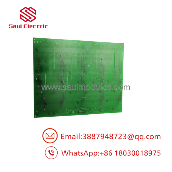
- DS200NATOG2A
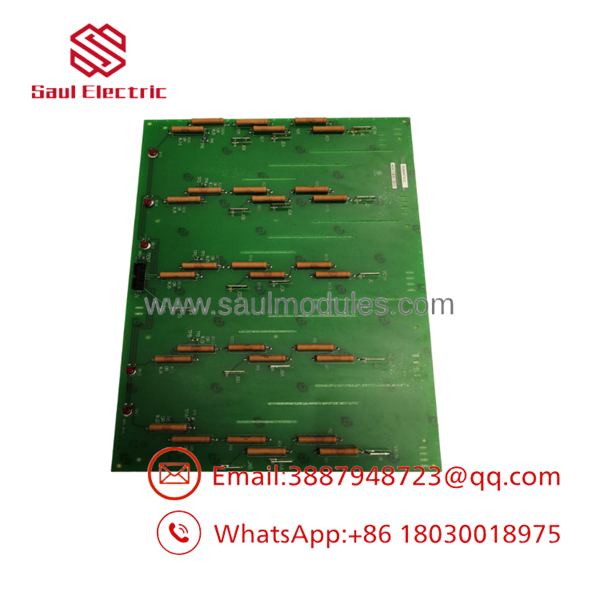
- DS200NATOG2A
The Veteran’s Tech Trap Guide
⚠️ Don’t assume every NATO board is identical.
The G2 version uses a different resistor and jumper arrangement than the earlier G1 hardware. Installing the wrong revision can produce incorrect voltage scaling without generating an obvious hardware alarm.
❗ Verify the stab connector positions before powering up.
The attenuation ratio depends on the stab connector configuration. Incorrect placement changes the measured bridge voltage and may trigger nuisance trips during startup.
⚠️ Inspect the ribbon cable carefully.
The board routes all five feedback channels through a 20-pin ribbon connector. Loose or damaged ribbon cables can create intermittent voltage feedback faults that are difficult to reproduce. The onboard MOVs help protect against open-circuit conditions, but they cannot compensate for poor connections.
❗ Don’t blame the NATO board first.
Before replacing it, verify the Gate Distribution Status Board and VME backplane. The NATO board depends on both assemblies for normal operation, and failures elsewhere in the signal chain can produce nearly identical symptoms.
Frequently Asked Questions (FAQ)
Q1. What does the do?
It attenuates high-voltage AC and DC signals from the SCR bridge into low-voltage feedback signals used by the LS2100 controller for voltage regulation and protection calculations.
Q2. Which GE systems use this board?
The board is designed for GE LS2100 Load Commutated Inverter (LCI) systems and is commonly associated with Mark V turbine control applications.
Q3. What is the difference between the G1 and G2 versions?
The G2 version replaces two lower resistors in each voltage divider string with wire jumpers, resulting in four resistors per string instead of six. This changes the hardware configuration, so revisions should not be interchanged without verification.
Q4. Does the board contain burden resistors?
No. The burden resistors required for operation are located on the Gate Distribution Status Board, not on the itself.
Q5. Why do these boards usually fail?
Typical causes include thermal aging of precision resistors, surge events, contamination, vibration, damaged ribbon connectors, or prolonged operation in high-temperature control cabinets.
Q6. Can this board be replaced without changing software?
Yes. If the replacement has the identical part number and hardware revision, no software changes are normally required. After installation, verify voltage scaling, converter diagnostics, and bridge feedback before returning the LCI system to service.
Q7. What warranty is typically provided?
Most industrial automation suppliers provide a 12-month warranty on functionally tested new surplus or professionally refurbished boards. Before commissioning, verify the G2 hardware revision, stab connector configuration, ribbon cable integrity, and compatibility with the associated Gate Distribution Status Board and VME backplane.



 Start Chat


