





Description
Product Introduction
The GE DS200TCDAG1B (TCDA) is a core Digital I/O Processing Board designed for GE Speedtronic Mark V turbine control systems and EX2100 static excitation panels. Stationed inside the digital I/O cores (such as the , , and cores), this card acts as the central traffic controller for discrete plant contact inputs and relay driver commands. It buffers incoming digital signals from field contact terminal boards (like the DTBA and DTBB) before routing them across the IONET bus to core processor boards.
Equipped with its own onboard microprocessor and socketed PROM firmware chips, the TCDA board takes the processing burden off the main rack processors by handling local signal conditioning, debounce filtering, and contact state monitoring. Its front-facing 10-LED diagnostic array provides instant visual verification of logic states and comm link health, letting I&C technicians diagnose contact status changes on the fly without patching in an external maintenance terminal.
Key Technical Specifications
| Parameter | Specification |
| Manufacturer | General Electric (GE) |
| Part Number | DS200TCDAG1B (Functional Designation: TCDA) |
| System Compatibility | GE Mark V Speedtronic / EX2100 Excitation |
| Processor Architecture | Onboard Microprocessor with socketed EPROM/PROM modules |
| Bus Interface | IONET local system bus communication |
| Visual Indicators | 10-LED diagnostic block + 1 status LED on board edge |
| Interconnects | 2 x 50-pin ribbon cable headers (JX1, JX2) + 7 secondary connectors |
| Configuration Options | 8 hardware jumper locations (J1 through J8) |
| Primary Signals Handled | Discrete contact inputs, relay feedback, and trip status lines |
| Coating Type | Standard conformal coating for industrial environments |
Application Scenarios & The “Trench” Experience
Picture this: It’s 1:45 AM during a torrential thunderstorm. Your 150MW steam turbine suddenly trips on a false “Lube Oil Pressure Low – Tripped” permissive alarm. The turbine comes down hard, but physical pressure gauges on the skid show rock-solid 45 PSI oil pressure. You open up the Mark V cabinet, pull up the diagnostic logs, and realize a failed digital input channel on the TCDA card latched low due to an internal optocoupler failure. When a TCDA card degrades, false trips can paralyze your entire generation asset in seconds.
- Combined-Cycle Power Plants – Mark V & Control Cores – Processes critical trip permissives, breaker auxiliary contacts, and valve position limit switches.
- Gas Turbine Speedtronic Retrofits – Frame 7 / Frame 9 Controllers – Conditions high-density digital contact inputs from field barrier blocks across IONET.
- Generator Excitation Cabinets – EX2100 Static Excitation Systems – Handles contact command inputs and interlock status lines for generator field flashing.
Field Case Study: A chemical plant’s cogen unit experienced recurring intermittent contact faults on its Mark V core, preventing turbine startup sequences. Our field tech dispatched a tested DS200TCDAG1B replacement card overnight. After swapping the EEPROM chips from the original board and matching jumper blocks J4 through J6, the panel cleared all IONET diagnostic faults on power-up. Total downtime was limited to under 3 hours, avoiding an expensive plant steam loss.
Transparency SOP: Quality Assurance & Testing
We treat legacy turbine control boards with the extreme care they demand. Every DS200TCDAG1B goes through our strict 5-step testing SOP before leaving the bench:
- Inbound Visual & Anti-Counterfeit Inspection: High-magnification check for trace oxidation, burnt resistor arrays, cracked PROM sockets, and unapproved solder repairs.
- 50-Pin Cable & Header Continuity Testing: Pin-by-pin continuity checks on JX1/JX2 connectors to catch bent pins or micro-fractures in solder pads.
- Live Mark V Rack Simulation: Board is installed in a powered GE Mark V test rack. Microprocessor boot sequence, memory reads, and IONET handshake are fully validated.
- Digital I/O Channel Stress Test: Injection of dynamic 24VDC/125VDC logic signals across input channels to verify optocoupler response and LED status block tracking.
- Static Mitigation & Shipping Prep: Cleaned, fitted with ESD protective caps, vacuum-sealed in anti-static shielding bags, and packed in high-density custom foam.
The Veteran’s Tech Trap Guide (Crucial Value-Add)
⚠️ 1. Transfer the EPROM/PROM Chips First: The DS200TCDAG1B relies on socketed firmware PROMs containing your specific turbine’s unit configuration and I/O mapping. If you drop a fresh replacement card into your rack without swapping your original firmware chips over, the Mark V core will fail to boot and throw a checksum/configuration fault!
❗ 2. Respect Jumpers J4, J5, and J6 (IONET Address): Jumpers J4 through J6 dictate the IONET bus address for the board. If you are replacing a TCDA in the core, its jumper address is completely different from a TCDA sitting in the core. Double-check every jumper position against the old card before seating the board.
⚠️ 3. Handle 50-Pin Ribbon Cables with Care: The 50-pin ribbon cables plugged into JX1 and JX2 carry ultra-fine insulated conductors. Never pull on the ribbon material itself to disconnect them—always grip the connector body evenly. A micro-fracture inside an aging 50-pin cable will create random, hard-to-trace intermittent I/O drops.
❗ 4. Watch Out for J7 (Stall Timer) & J8 (Test Mode): Jumper J7 controls the onboard watchdog stall timer, and J8 enables diagnostic test mode. Leaving J8 jumpered in the “Test” position after bench work will prevent the board from processing live field contact inputs in auto mode!
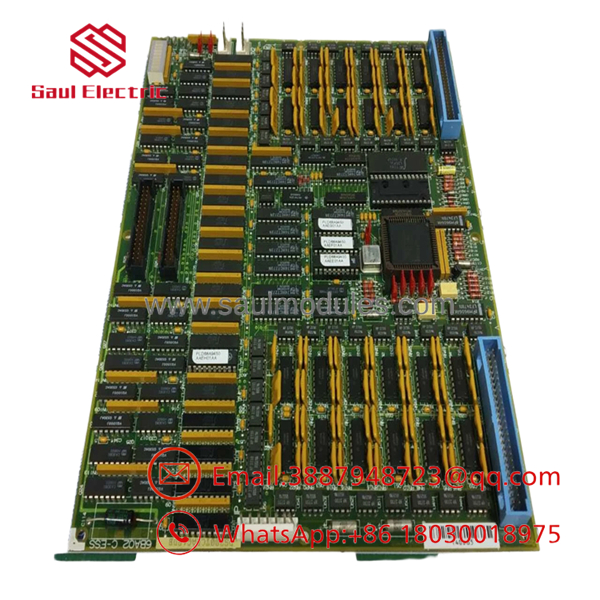
DS200TCDAG1B
Frequently Asked Questions (FAQ for Conversion)
Q: Is the GE DS200TCDAG1B hot-swappable?
A: No. You must never pull or insert this card while the Mark V core cage is powered. Removing a digital I/O card under power risks disrupting the IONET communication loop for the entire core and can cause unpredictable relay trips across the running turbine.
Q: What is the difference between and DS200TCDAG1BDB?
A: The “DB” suffix indicates a specific artwork/revision level of the base TCDA board. The “1B” represents the primary functional revision level. In almost all instances, a DS200TCDAG1BDB is a direct drop-in replacement for any earlier TCDA 1A or 1B card, provided jumper settings and firmware PROMs are transferred.
Q: Do I need special software tools to configure this card upon installation?
A: No software download to the board itself is required if you transfer the original socketed firmware PROMs from your old TCDA board. Once the PROMs are moved and the jumpers match, the core processor will auto-detect the card on bootup.
Q: Are these units clean surplus or pulled from active service?
A: Because GE phased out Mark V production, these units are sourced from New Surplus warehouse inventories or Fully Refurbished / Bench-Tested panels from decommissioned plants. Every card passes full dynamic I/O rack testing before entering our ready-to-ship stock.
Q: What warranty coverage do you provide on legacy Speedtronic cards?
A: We provide a full 12-month replacement warranty on all units. If the board fails or triggers bus communication errors under normal operating conditions within one year, we will send an immediate advance replacement.



 Start Chat


