





Description
Key Technical Specifications
| Parameter | Value |
|---|---|
| Manufacturer | GE |
| Model Number | DS200TCQCG1BGF |
| Product Type | Analog I/O Expander Board |
| System Platform | GE Mark V Speedtronic |
| Form Factor | 6U Eurocard PCB |
| Installation | Card cage slot installation |
| Power Supply | Backplane supply from TCPS board |
| Operating Supply | +5 V DC, ±15 V DC, +24 V DC (backplane supplied) |
| Primary Functions | Servo output conditioning, pulse-rate processing, analog signal interface |
| Configuration | Hardware jumpers |
| Operating Temperature | 0 °C to +50 °C |
| Storage Temperature | -40 °C to +85 °C |
Product Introduction
The GE DS200TCQCG1BGF is an Analog I/O Expander Board used in the GE Mark V Speedtronic turbine control system. It interfaces with multiple control boards to process servo commands, pulse-rate feedback, generator signals, and analog field signals required for gas and steam turbine operation.
In field maintenance, this board is commonly replaced during scheduled outages or after hardware diagnostics identify a failed analog interface. Before installation, verify the board revision, jumper configuration, and firmware compatibility with the existing Mark V cabinet to prevent commissioning delays.
Troubleshooting Quick Reference
| Symptom | Possible Cause | Relevance to this Part | Quick Check Method | Recommendation |
|---|---|---|---|---|
| Servo valve not responding | Servo output circuit fault | ✅ High | Measure servo output current and inspect relay operation | Verify board diagnostics before replacement |
| Turbine speed feedback missing | Pulse-rate input failure | ✅ High | Measure magnetic pickup signal at connector | Inspect wiring before replacing the board |
| Communication alarm from Mark V | Connector or backplane issue | ✅ Medium | Reseat board and inspect Eurocard connector | Clean contacts and retest |
| Analog signals unstable | Loose field connector | ✅ Medium | Verify terminal continuity and shielding | Tighten wiring and inspect grounding |
| Board not detected | Backplane power missing | ❌ Low | Measure +5 V DC and ±15 V DC at backplane | Repair power supply before replacing board |
| Unexpected trip during startup | Incorrect jumper configuration | ✅ High | Compare jumper settings with original board | Duplicate original hardware configuration |
| Multiple I/O alarms | External wiring fault | ❌ Low | Verify field wiring with OEM drawings | Eliminate field wiring issues first |
Technical Note: This board rarely fails without an external cause. Power supply instability, damaged field wiring, connector oxidation, or incorrect jumper settings account for many reported failures. If troubleshooting remains inconclusive, collect controller diagnostics, LED status, board photos, and wiring information before replacing the module.
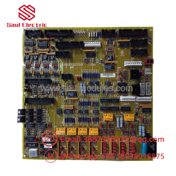
- DS200TCQCG1BGF
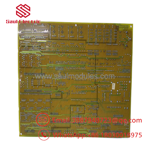
- DS200TCQCG1BGF
Frequently Asked Questions (FAQ)
Q1. Is the GE DS200TCQCG1BGF still available?
Yes, but it is a legacy Mark V component. Most available inventory consists of New Surplus or professionally tested surplus units because OEM production has ended.
Q2. Is this board compatible with every Mark V system?
Not necessarily.
Verify the exact part number, board revision, and cabinet configuration. Similar DS200 boards often perform different functions and are not interchangeable.
Q3. Can I hot-swap this board?
No.
The Mark V control cabinet was not designed for routine hot swapping of controller boards. Remove power according to plant lockout/tagout procedures before replacing the module.
Q4. Do I need to configure jumpers after installation?
Yes.
This board relies on hardware jumper settings for several functions. Photograph the original board before removal and duplicate every jumper position exactly. This simple step prevents many startup problems.
Q5. Why is New Surplus inventory less expensive than factory supply?
New Surplus inventory typically originates from canceled projects, unused maintenance stock, or excess OEM inventory. The board has not been installed in production service but is no longer manufactured.
Q6. Does replacing the board require calibration?
Generally, no field calibration is required. However, verify jumper settings, perform functional checks, and confirm all analog signals before returning the turbine to service.
Q7. What warranty is typically offered?
Most industrial automation suppliers offer a 12-month warranty on verified New Surplus or fully tested units. Request the functional test report and inspection records before shipment.
Quality Inspection & Testing SOP
1. Inbound Inspection & Traceability
- Verify GE part number, revision code, serial number, and manufacturing labels.
- Inspect PCB for corrosion, damaged traces, bent connector pins, solder rework, or UV discoloration.
- Confirm all jumpers, relays, and connectors are present.
- Record serial numbers for complete traceability.
2. Live Functional Testing
- Install the board in an in-house GE Mark V test rack.
- Verify normal power-up and communication with companion boards.
- Test servo output circuits and pulse-rate input channels.
- Simulate analog inputs and monitor board response.
- Operate continuously for more than 24 hours while monitoring temperature.
- Generate a documented functional test report.
- Test photos and videos are available upon request.
3. Electrical Parameter Testing
- Measure insulation resistance using a 500 V Megger where applicable.
- Verify ground continuity.
- Measure backplane voltages with a calibrated Fluke 115 multimeter.
- Confirm stable operation under continuous load.
4. Firmware & Configuration Verification
- Verify board revision.
- Photograph all jumper positions before shipment.
- Confirm hardware configuration matches the customer’s requested revision.
5. Final QC & Packaging
- QC inspector approval.
- Package inside an ESD-safe bag.
- Protect with anti-static foam, bubble wrap, and a heavy-duty corrugated carton.
- Apply a dated QC Passed label.
Technical Pitfalls & Survival Guide
❗ Firmware and Hardware Revision
I’ve seen technicians replace a perfectly good board only to discover the cabinet expected a different hardware revision. Always verify the complete suffix, not just the DS200 base number.
❗ Jumper Configuration
Take a photo before touching anything.
This is the most common installation mistake. One misplaced jumper can disable servo feedback or alter signal scaling.
❗ Connector Inspection
Don’t force the board into the card cage.
Inspect every connector for bent pins or oxidation. A poor backplane connection can produce intermittent faults that look like a defective board.
❗ Power Supply Verification
Measure the Mark V backplane voltages before replacing hardware. Low +5 V DC or ±15 V DC supplies frequently generate false board alarms.
❗ Electrostatic Discharge (ESD)
Always wear a grounded wrist strap.
I’ve watched an expensive turbine control board fail immediately after installation because it was handled without ESD protection on a dry winter day. The damage wasn’t visible, but the board never completed startup.
Keep these checks in mind and you’ll eliminate most installation errors, reduce unnecessary board replacements, and shorten turbine outage time.

 Start Chat


