





Description
Product Introduction & Engineering Value
Managing legacy Field Control I/O drops often means dealing with aging analog links that can throw your entire supervisory control loop off balance. The GE Fanuc IC670ALG230K gives you eight single-ended channels designed specifically for current-loop monitoring without forcing a full cabinet rebuild. It mounts straight onto standard Field Control I/O terminal bases, snapping in to handle raw 0–20 mA or 4–20 mA field signals with minimal fuss.
The module takes care of signal conditioning right at the point of entry. It converts analog current to digital values via an onboard ADC with a fast 60 µs/channel conversion speed. Analog scaling is then passed off to the local Bus Interface Unit (BIU), freeing up host processing cycles. For plants running legacy Field Control drops on Genius, Profibus-DP, or DeviceNet, stocking a fresh IC670ALG230K is the fastest way to protect continuous process monitoring from unexpected loop failure.
Technical Specifications
- Number of Channels: 8 single-ended current inputs (single group)
- Configurable Signal Ranges: 0 to 20 mA (default) or 4 to 20 mA per channel
- Input Impedance: 250 Ω (\pm0.25 Ω precision shunt resistor)
- Digital Resolution: 12 bits (5.0 µA per LSB)
- Conversion Time: 60 µs per channel typical (at 1 MHz ADC clock)
- Non-Linearity: \pm0.025% of full scale
- Maximum Accuracy Error: \pm0.05% full scale at 25°C (0.1 mA < I_{in} < 20 mA)
- Isolation: 1500 VAC ground-to-logic (1 minute); 250 VAC continuous to case
- Field Power Input: 24 VDC nominal (18–30 VDC external range)
- Current Draw: 51 mA maximum from BIU power supply
- Input Filter Type: 1st order RC filter with 160 Hz transition frequency
Field Application & The “Trench” Experience
The Slurry Pump House Loop Drift
During an off-shift callout at a municipal wastewater plant, operators noticed erratic flow readings on a primary sludge transfer pump. The local Field Control node was returning fluctuating values, causing the main PLC to constantly trip the VFD speed command. A quick multimeter check across the terminal block revealed that an internal 250 Ω precision sensing resistor on channel 3 of the original 1990s-era IC670ALG230 input card had drifted out of tolerance due to years of heat cycling in an unconditioned panel.
The technician unlatched the module from the I/O terminal base, leaving all field wiring undisturbed on the block. After setting the replacement IC670ALG230K card into place and cycling 24 VDC power to the BIU, the module auto-configured over the backplane. Channel 3 immediately stabilized at a steady 12.4 mA, getting the sludge pumps back online within 20 minutes without touching a single screwdriver to the field wiring.
Key Deployment Scenarios
- Catalytic Cracking Unit Temperature & Pressure Tracing: Reading 4–20 mA loops from 2-wire temperature transmitters across hazardous plant areas.
- Chemical Dosing Skid Flow Monitoring: Capturing high-speed pulse-to-current flowmeter feeds using the 60 µs conversion time to maintain accurate batch ratios.
- Paper Mill Headbox Level Feedback: Interfacing differential pressure transmitters to a distributed Field Control Genius drop.
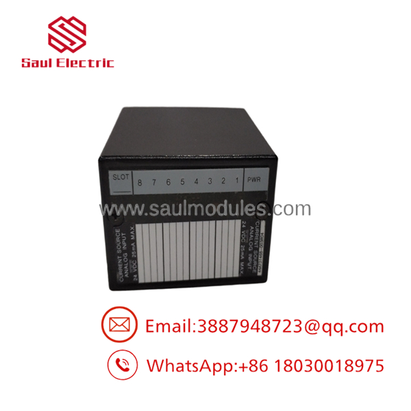
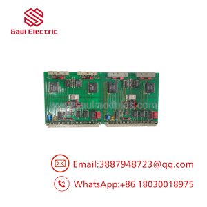
- IC670ALG230K
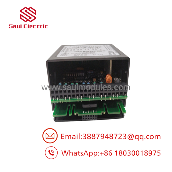
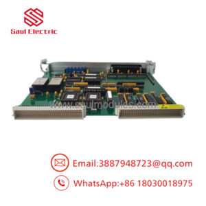
- IC670ALG230K
Transparency SOP: QA & Testing
- Step 1: Visual Inspection & Revision Verification
We audit the board housing for cracked retention clips, check terminal connector pins for oxidation, and confirm the hardware revision print (Revision K update).
- Step 2: Bench Power & Bias Current Verification
The module is mated to a test terminal block and powered with an external 24.0 VDC supply. Backplane BIU logic current draw is benchmarked against the 51 mA maximum threshold.
- Step 3: 8-Channel Precision Signal Injection
Using a calibrated Fluke 754 process calibrator, we sweep current inputs from 0.00 mA to 20.00 mA in 2.00 mA increments across all 8 channels simultaneously. Digital conversion values are checked across the entire span to verify 12-bit linearity (\le \pm0.025\%).
- Step 4: Open-Wire & Over-Range Fault Diagnostics
We test fault signaling by forcing current above 20.5 mA (over-range trigger) and dropping input below 2.0 mA on 4–20 mA configuration to confirm that the BIU correctly flags open-wire status bits.
The Veteran’s Tech Trap Guide (Crucial Value-Add)
⚠️ TRAP 1: Missing Loop Power Jumpers on 2-Wire Sensors
The IC670ALG230K is a current-sinking input module; it does not provide loop power directly on the signal terminals unless wired to the auxiliary 24V supply on the base block. If you are wiring 2-wire unpowered transmitters, you must supply 24 VDC to the loop. Forgetting this jumper is the #1 reason engineers think a newly installed replacement card is “dead on arrival.”
⚠️ TRAP 2: Common-Ground Loop Interference
Because all 8 channels share a single common return on the base block, connecting multiple 4-wire grounded transmitters can create sneaky ground loops. If your signal values jump around when a second field device powers up, you are facing a common-mode voltage breakdown. Use isolated signal conditioners or ungrounded 2-wire loops when running across long field cable runs.
PRO TIP: Understanding the Revision “K” Delta
Later hardware revisions like the K revision incorporate improved ESD protection components and tighter tolerance shunt resistors over earlier releases (such as revisions A through F). When replacing an older revision, no software changes or BIU configuration updates are required—it is 100% backward compatible drop-in hardware.
Dynamic FAQ
Q: Can I mix 0–20 mA and 4–20 mA ranges on different channels of the same module?
A: Yes. Signal ranges (0 to 20 mA or 4 to 20 mA) are software-configurable on a per-channel basis through your Bus Interface Unit (BIU) software setup. The factory default for all channels is 0 to 20 mA.
Q: What happens if a field wire breaks on a 4–20 mA channel?
A: When configured for 4–20 mA, the module includes open-wire detection. If the loop current drops below approximately 2.0 mA, the module reports an open-wire fault bit back through the BIU to the host controller for easy alarming.
Q: Do I need to disconnect field wiring when replacing an old module with this revision?
A: No. Field Control uses a two-piece architecture. All field wiring lands on the permanent I/O terminal block base. The electronics module simply snaps off the base, allowing hot-swapping or rapid replacement without touching terminal screws.
Q: What is the input impedance of the channel inputs?
A: Each input channel uses a high-precision internal shunt resistor rated between 249.75 Ω and 250.25 Ω (nominally 250 Ω).
Q: What warranty comes with your surplus or refurbished units?
A: Every module shipped includes a comprehensive 12-month full-replacement warranty, packaged in anti-static ESD protection following full 8-channel loop calibration testing.

 Start Chat


