





Description
Product Introduction & Engineering Value
Managing tight control panels where every inch of DIN rail counts usually means sacrificing resolution or buying expensive high-density racks. The GE VersaMax IC200ALG264H eliminates that compromise by cramming 15 high-precision analog current channels into a single standard VersaMax slot. Engineered for continuous process loops, it delivers 15-bit resolution across both 4–20 mA and 0–20 mA operating ranges.
Operating without requiring an external logic power connection, the card draws its minimal 100 mA operational power directly from the 5 VDC backplane bus. Built-in diagnostic capabilities automatically flag internal power drops and open-wire line faults on active 4-20 mA channels, giving remote maintenance teams rapid visibility into field wiring failures before process upsets occur.
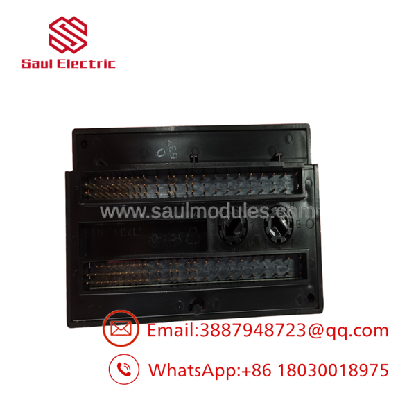
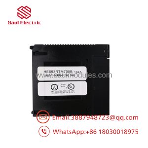
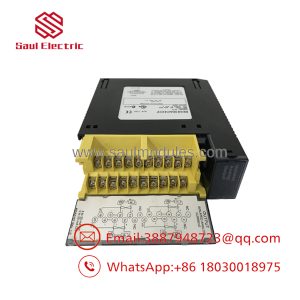
- IC200ALG264H
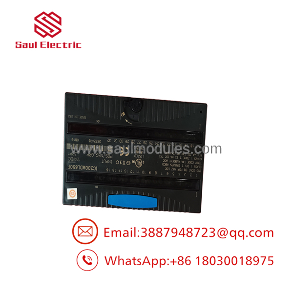
- IC200ALG264H
Technical Specifications
| Parameter | Specification |
| Channels | 15 single-ended channels (1 common return group) |
| Input Current Ranges | 4–20 mA (default, no jumper) / 0–20 mA (jumper installed) |
| Resolution | 15-Bit (0.5 µA/count @ 4-20mA; 0.625 µA/count @ 0-20mA) |
| Input Impedance | 100 Ω |
| Module Update Rate | 7.5 ms for all 15 active channels |
| Accuracy (25°C) | ±0.3% typical / ±0.5% maximum of full scale |
| Filter Response (3dB) | 24 Hz (±20%) |
| Backplane Current Draw | 100 mA @ 5 VDC max |
| Isolation Rating | 250 VAC continuous / 1500 VAC for 1 minute (Field-to-Logic) |
| Diagnostics | Loss of internal field supply, Open-wire detection (4-20mA mode) |
Field Application & The “Trench” Experience
During an emergency line restoration at a bulk liquid tank farm, the client’s telemetry system lost communication with 12 radar level transmitters due to a failed legacy 8-channel rack setup. Space inside the outdoor Marshalling cabinet was extremely constrained. We mounted an IC200ALG264H on a compact terminal carrier, landed all 12 transmitter signal lines onto the shared common rail using an auxiliary shorting bar, and mapped the full array into Machine Edition in under 45 minutes—restoring real-time inventory tracking without adding extra DIN rail space.
Niche Application Scenarios:
- Multi-Zone Annealing Ovens: High-density logging of 15 current loops connected to pyrometer signal converters.
- Municipal Lift Station Monitoring: Polling multiple wet-well level sensors, pump vibration 4-20mA transmitters, and line pressure transducers on a single card.
- Flue Gas Scrubbers: Monitoring distributed pH, turbidity, and flow transmitters operating on long 4-20mA current loops.
Transparency SOP: QA & Testing
- Physical & Revision Verification: Board-level check confirming authentic ‘H’ revision status, backplane edge finger condition, and carrier locking mechanism integrity.
- 5V Backplane Bus Test: Bench test confirming logic current consumption holds steady at 100 mA @ 5 VDC.
- 15-Channel Current Loop Calibration: Sweeping 4.00 mA to 20.00 mA using a Fluke loop calibrator across every channel, verifying 15-bit conversion counts (0 to 32,000) in PLC logic.
- Range Jumper & Diagnostic Check: Testing open-wire detection triggering in 4-20mA mode (line break simulation) and verifying 0-20mA transition when installing the A16-A17 terminal jumper.
- Continuous Heat-Load Run: 4-hour burn-in under full loop excitation to ensure zero thermal drift across the ADC stages.
The Veteran’s Tech Trap Guide
- ⚠️ Range Selection via Terminal Jumper: To switch the entire module from 4–20 mA mode to 0–20 mA mode, you must install a physical jumper wire between carrier terminals A16 and A17. If left unjumpered, the module defaults to 4–20 mA operation.
- PRO TIP: Common Return Noise Vulnerability! Because all 15 channels are single-ended and share a single common return, running unshielded cables across noisy VFD conduit runs will induce cross-channel crosstalk. Always use shielded twisted pairs and ground the shields to an Auxiliary Terminal Strip (IC200TBM001).
- ⚠️ Open-Wire Fault Condition: Open-wire diagnostic reporting only functions in 4-20 mA mode. If you run 0–20 mA mode, a severed cable will simply register as 0 mA (0 counts) without generating a diagnostic fault flag in the CPU.
Dynamic FAQ
Q: What does the “H” suffix in IC200ALG264H mean?
A: The “H” designates a specific factory hardware revision level. Revision H features minor manufacturing updates and label refresh releases while remaining 100% backward compatible in form, fit, and function with earlier revisions (A through G).
Q: Does the IC200ALG264H supply loop power to 2-wire transmitters?
A: No. The card processes signal currents and powers its internal ADC from the 5V backplane, but external 24 VDC power must be wired in series to loop-power 2-wire transceivers.
Q: Can I configure individual channels for 0-20mA while keeping others at 4-20mA?
A: No. The current range selection (jumper between A16 and A17) applies to the entire 15-channel group simultaneously.
Q: What warranty comes with New Surplus or Refurbished units?
A: Every unit passes full 15-channel calibrator testing and ships backed by a 1-Year replacement warranty.

 Start Chat


