





Description
Product Introduction & Engineering Value
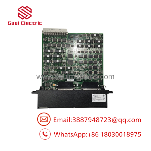
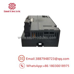
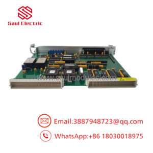
Managing critical process uptime means your hot standby switchovers cannot afford a single dropped scan cycle. The GE Fanuc IC687RCM711 Redundancy Communications Module (RCM) acts as the dedicated high-speed inter-CPU link for Series 90-70 redundant racks. By offloading CPU memory synchronization, state table mirrors, and shared I/O tracking onto a dedicated hardware interface, the IC687RCM711 ensures that the secondary unit stays in perfect lockstep with the primary controller.
Instead of relying on network-level software handshakes that consume precious PLC scan time, this single-slot VME module utilizes direct parallel bus expansion to achieve transfer rates up to 500 KB/sec. Featuring a front-panel manual toggle switch for controlled maintenance switchovers and real-time status diagnostics, the IC687RCM711 provides the deterministic hardware foundation needed to keep legacy power generation, water treatment, and chemical processing skids online.
Technical Specifications
- Form Factor: Single-slot VME C.1 standard width
- Module Type: High-Speed Parallel Bus Redundancy Interface
- Power Requirements: 1.2 Amps maximum from 5 VDC backplane bus
- Effective Data Transfer Rate: 500 Kbytes/second
- Maximum Interconnect Distance: 50 feet (15 meters) via specialized IC600WD series shielded cable
- Compatible CPUs: Series 90-70 HSB/FIP CPUs (e.g., IC697CFR782, IC697CFR28, CPU782)
- Isolation: Non-isolated high-speed differential bus interface
- Status LEDs: 5 front-panel indicators (BOARD OK, LOCAL READY, LOCAL ACTIVE, REMOTE READY, REMOTE ACTIVE)
- Manual Override: Recessed front-panel pushbutton for manual Active-to-Backup switchover
- Minimum Switchover Hold-off: 10-second forced delay between successive manual switchover commands
Field Application & The “Trench” Experience
The Co-Gen Plant Unscheduled Tripping Incident
At a gas turbine co-generation plant, the primary Series 90-70 rack repeatedly failed to pass CPU mirror data to the backup rack, raising alarms in the DCS and threatening a forced trip during peak generation hours. The maintenance crew found that an aging IC687RCM711 module in Rack B was intermittently dropping the REMOTE READY status. Cable testing confirmed the IC600WD interconnect line was intact, pointing directly to transceiver degradation on the RCM board’s VME bus interface.
Because the system was configured for single-rack/dual-rack hot standby, the technician pressed the manual switchover button on the Active RCM to lock control cleanly onto Rack A. With Rack B safely disarmed, they unlatched the failing IC687RCM711 board and installed a pre-tested replacement. Upon repowering Rack B, the RCM completed its hardware handshake, established the 500 KB/s sync link, and turned the LOCAL READY LED solid green—restoring full HSB fault tolerance without tripping the turbine.
Core Application Environments
- Gas & Steam Turbine Control (Mark VI / 90-70 Hybrid Systems): Maintaining real-time CPU memory synchronization across dual-redundant speed control loops.
- Continuous Chemical Reactor Control: Guaranteeing seamless 0 ms bump-free switchover for safety-instrumented emergency shutdown (ESD) routines.
- Municipal Water Pumping Mainlines: Linking dual Series 90-70 PLCs to prevent hydraulic water hammer during controller maintenance.
Transparency SOP: QA & Testing
- Step 1: Visual & VME Connector Audit
We inspect the module for heat discoloration, check board traces for solder fatigue, and verify that all VME backplane pins are straight, unoxidized, and fully intact.
- Step 2: 5V Power Rail & Thermal Stressing
The RCM board is installed in a Series 90-70 rack and powered at 5.0 VDC under thermal soak conditions to confirm current draw remains steady at the 1.2A specification.
- Step 3: Dual-Rack High-Speed Mirror Testing
The module is paired with a secondary RCM across a 25 ft IC600WD cable in a dual-CPU test rig. We force continuous 500 KB/s memory transfers while monitoring register sync, packet drop rates, and differential signal integrity via oscilloscope.
- Step 4: Manual Switchover & Timeout Validation
We actuate the front-panel pushbutton to verify immediate, bump-free switchover between LOCAL ACTIVE and REMOTE ACTIVE states. The 10-second anti-chatter switchover lock is functionally verified.
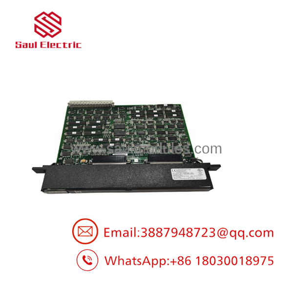
- IC687RCM711
The Veteran’s Tech Trap Guide (Crucial Value-Add)
⚠️ TRAP 1: The 10-Second Anti-Chatter Switchover Lock
When using the front-panel manual switchover pushbutton, the module enforces a hard 10-second delay before allowing another switchover. If you press the button to shift control to the backup rack and immediately attempt to press it again to toggle back, the RCM will ignore the command. Do not assume the switch is broken—wait at least 10 full seconds for the system state machine to settle.
⚠️ TRAP 2: Using Standard Expansion Cables Instead of IC600WD Series
The uses a high-speed, non-isolated differential bus running at 500 KB/sec. Attempting to substitute standard VME or custom ribbon cables for the official factory IC600WD005 / 010 / 025 / 050 cables will introduce signal reflections and timing jitter. Always use factory-terminated IC600WD cables to ensure proper 75/120 ohm line impedance matching.
PRO TIP: Interpreting LED Diagnostic Combinations
Always check the LED indicators before pulling a module. If BOARD OK is ON but REMOTE READY is OFF, the problem is rarely the local CPU; it indicates either a disconnected IC600WD cable, a powered-down remote rack, or a configuration mismatch in the Logic Developer/VersaPro hardware settings between the two racks.
Dynamic FAQ
Q: Can I hot-swap the module while the Series 90-70 rack is under power?
A: No. Series 90-70 VME backplanes do not support live hot-swapping of core CPU or redundancy communication cards. Always power down the specific rack before removing or inserting the board to prevent backplane bus crashes or board damage.
Q: Does the require a dedicated software driver?
A: No separate driver is required. However, the module must be properly defined in your Series 90-70 rack configuration (using Logic Developer PLC, VersaPro, or MS-DOS Logicmaster 90-70). The hardware configuration sets the memory buffer sizes and sync intervals.
Q: What cable length options are supported for connecting dual RCM modules?
A: GE Fanuc specifies pre-terminated cables in lengths of 5 feet (1.5m), 10 feet (3m), 25 feet (7.5m), and 50 feet (15m). 50 feet is the absolute maximum supported distance for reliable 500 KB/s data transfer.
Q: What is the primary cause of a “REMOTE READY” LED failing to turn on?
A: This typically stems from an offline remote CPU, a disconnected or damaged interconnect cable, or a software checksum mismatch where the program in the backup rack does not match the active rack.
Q: What warranty is included with your surplus or refurbished modules?
A: All modules—whether refurbished or certified new surplus—are fully bench-tested in a live dual-rack test rig and come backed by our standard 12-month full-replacement warranty.

 Start Chat


