





Description
Product Introduction & Engineering Value
Why clutter your enclosure with separate cards for transmitters and panel potentiometers? The GE VersaMax IC200ALG260 tackles mixed-signal density head-on by packing 8 software/hardware-selectable analog input channels into a compact, snap-on VersaMax footprint. Whether reading ±10V motor drive feedback, 0-10V position sensors, or 4-20mA process loops, this card handles signal conversion at a rapid 0.4 ms module update rate.
By utilizing 12-bit converter resolution, the card converts process variables cleanly into 16-bit CPU registers (%AI). Optically isolated up to 1500 VAC from the backplane, it shields your main VersaMax CPU or Network Interface Unit (NIU) from high-voltage field surges and common-mode noise spikes.
Technical Specifications
- Number of Channels: 8 single-ended channels (1 common return group)
- Input Signal Ranges: ±10 VDC (default), 0 to 10 VDC, or 4–20 mA current
- Resolution: 12-Bit (2.5 mV = 8 counts in Voltage mode; 4 µA = 8 counts in Current mode)
- Backplane Power Consumption: 130 mA @ 5 VDC (Drawn directly from backplane bus)
- External Field Power: None required for logic board; 2-wire transceivers require external loop supply
- Input Impedance: 126 kΩ max (Voltage Mode) / 200 Ω max (Current Mode)
- Filter Response Time: 5.0 ms
- Module Update Rate: 0.4 ms across all active channels
- Isolation Rating: 250 VAC continuous / 1500 VAC for 1 minute (Field-to-Logic)
- Diagnostics: Loss of Internal Power, Over/Under Range detection
Field Application & The “Trench” Experience
During an emergency retrofit on a pharmaceutical water purification skid, two existing 4-channel analog cards failed after a power surge destroyed their input front-ends. Panel space was at an absolute premium. We dropped a single IC200ALG260 onto a two-row box carrier (IC200CHS002). By jumpering the carrier pins for 4-20mA operation on channels 1–4 (pressure transducers) and 0-10V on channels 5–8 (flow meters), we consolidated two failed modules into one footprint and had the skid logging data within 30 minutes.
Niche Application Scenarios:
- HVAC Air Handling Units: Monitoring 0-10V damper positioners and 4-20mA duct static pressure sensors on a single VersaMax rack.
- Plastics Injection Molding: High-density reading of 0-10V linear displacement transducers alongside melt temperature 4-20mA transmitters.
- Pumping Station Monitoring: Polling multi-point suction/discharge pressure transmitters across 8 single-ended field loops.
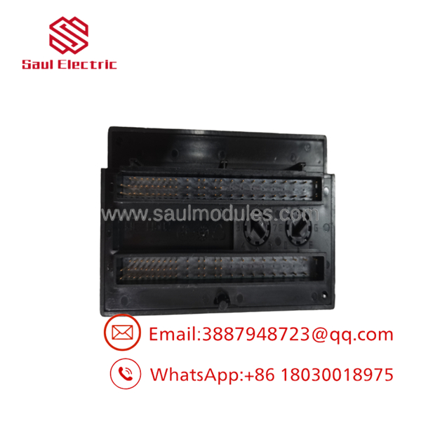
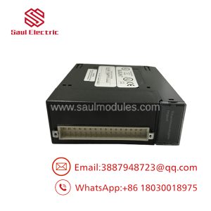
- IC200ALG260
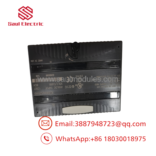
- IC200ALG260
Transparency SOP: QA & Testing
To ensure every New Surplus or Remanufactured IC200ALG260 operates flawlessly in high-speed control systems, our engineering shop subjects each unit to a 5-step checkout:
- Carrier Latch & Pin Inspection: Inspection of the module’s backplane connector pins and carrier release latches for mechanical wear or alignment faults.
- 5V Bus Consumption Verification: Bench check ensuring backplane current draw holds steady at ~130 mA @ 5 VDC without internal rail sag.
- Hardware Jumper & Carrier Validation: Verification of voltage/current mode response using VersaMax I/O carriers (IC200CHS series).
- 8-Channel Signal Injector Test: Precision injection across all 8 channels using a calibrator—sweeping 0–10V and 4–20mA while monitoring bit-count stability in Machine Edition.
- LED Diagnostics Check: Confirming “OK” (Backplane Power) and “INT PWR” (Internal Field Power) illuminate correctly under full rack initialization.
The Veteran’s Tech Trap Guide
- ⚠️ Carrier Jumpers Control the Mode: Unlike some PLC modules where input ranges are set 100% in software, the IC200ALG260 relies on physical jumpers (or terminal wiring) on the VersaMax I/O carrier to select current mode vs. 0-10V unipolar mode. If your 4-20mA signal reads zero or pegs full scale, check if the carrier jumpers (JMP1 / JMP2) were forgotten during installation!
- PRO TIP: Single-Ended Return Trap! All 8 channels share a single common return (Return/Common terminals). If you are connecting 4-wire transmitters that do not share a common ground reference, ground loops can skew your readings across adjacent channels. Use signal isolators if floating ground potentials exist between field devices!
- ⚠️ Transmitter Loop Power: The does NOT supply loop power to 2-wire current transmitters. You must route an external 24 VDC power supply in series with your field loops.
Dynamic FAQ
Q: Does the require an external 24V supply to power its internal logic?
A: No. The logic circuitry and internal power are derived directly from the 5 VDC VersaMax backplane bus (drawing up to 130 mA). However, external field loop power (24 VDC) is required if you are wiring 2-wire current transmitters.
Q: Can I mix 4-20mA current inputs and 0-10V voltage inputs on the same card?
A: Yes. Channels can be wired or jumpered individually on the I/O carrier to handle either current or voltage signals per channel.
Q: What do the “OK” and “INT PWR” LEDs indicate on the front panel?
A: The green “OK” LED indicates that backplane power is present and logic communication is healthy. The “INT PWR” LED confirms that the internal power converter generating field-side circuitry voltage is operating properly.
Q: What is the warranty coverage on New Surplus and Refurbished units?
A: All units undergo full multi-point signal testing and are backed by a comprehensive 1-Year replacement warranty.

 Start Chat


