





Description
Key Technical Specifications
| Parameter | Specification / Value |
| Form Factor | 6U Eurocard (Standard VMEbus height) |
| VMEbus Compliance | ANSI/IEEE STD 1014-1987 IEC 821 and 297; Mnemonic: A16:D16/D08 (EO) DTB Slave |
| Address Space | Occupies 128 bytes in Short I/O (A16) space; configurable to any 64-word boundary |
| ADC Resolution | 12-bit right-justified digital values with built-in track-and-hold |
| Channel Capacity | 32 single-ended channels or 16 differential voltage channels |
| Aggregate Sampling Rate | 40,000 samples per second (40 kHz) continuously updated to dual-port memory |
| Jumper-Programmable Gains | x1, x10, x100 (±0.3 percent accuracy) |
| Selectable A/D Ranges | ±5 V, ±10 V, 0 to +10 V (Bipolar input ranges down to ±50 mV depending on gain) |
| Input Filter Options | Single-pole passive low-pass filter; -3 dB at 50 kHz or 40 Hz |
| Isolation | 1,000 VDC isolation between analog ground and digital ground |
| Overvoltage Protection | ±40 V maximum sustained (power applied); ±25 V (power removed) |
| Power Requirements | +5 VDC (±5 percent) at 1.5 A maximum |
| Front Panel Interface | 37-pin subminiature D female connector (P3) |
Product Introduction
The GE Fanuc VMIVME-3125 (332-003125-100) is a high-performance, 6U VMEbus-compliant analog-to-digital converter (ADC) module designed for legacy industrial automation, process monitoring, and real-time data acquisition environments. Originally manufactured by VMIC, this board processes up to 32 single-ended or 16 differential analog inputs, translating continuous sensor field signals into precise 12-bit digital values accessible across the VME backplane via dual-ported data registers.
By utilizing hardware-driven autoscanning, the VMIVME-3125 operates with zero software initiation overhead, digitizing active channels at an aggregate rate of 40 kHz. System integrators choose this module for legacy host applications due to its robust 1,000 VDC ground isolation, multi-range voltage/current adaptability, and integrated real-time Built-in-Test (BIT) diagnostics that maintain system visibility in demanding field deployments.
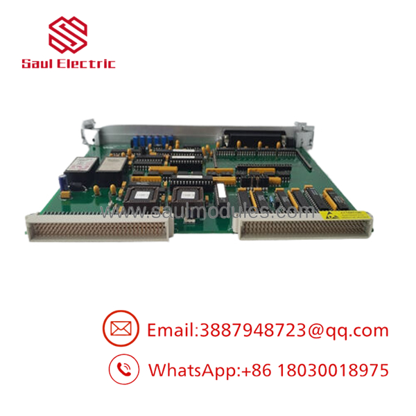
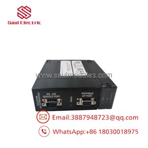
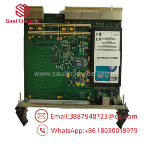
- VMIVME-3125
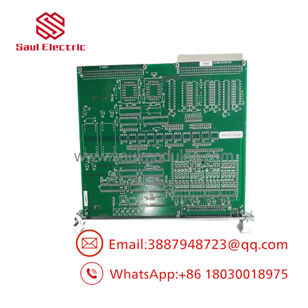
- VMIVME-3125
Troubleshooting Quick Reference
| Symptom | Possible Cause | Relevance to this Part | Quick Check Method | Recommendation |
| Front panel SYS FAIL LED remains constantly illuminated | Power-on self-test failure or unresolved System Reset state | ✅ High | Check if host system software has issued the command to turn off the LED post-boot. If power is good, BIT diagnostics failed. | Inspect board jumper placement. If host fails to clear the latch, the board’s internal ADC or control logic is compromised; replace unit. |
| All channel readings register at maximum scale or zero data output | Loss of +5 VDC backplane power or broken ground reference | ❌ Low | Measure the main power supply rails at the VME backplane pins. Check if the +5 VDC line dips below 4.75 VDC under load. | If backplane power is stable and within 1.5 A delivery limits, pull the board and inspect for bad connections on the J1/J2 backplane connectors. |
| Erratic data fluctuations or ghost voltages across inactive channels | Floating inputs caused by missing pull-down paths or ground loops | ✅ High | Verify that the 22 MΩ internal pull-down resistors are grounded, or check line-to-common input impedance using a Fluke 115 multimeter. | Ensure proper shielding and common-mode reference wiring on the 37-pin D-sub connector. Switch channels to true differential mode if ground loops persist. |
| Host system generates a VMEbus timeout error (Bus Error) when accessing board | Base address jumper mismatch or conflicting address modifier configuration | ✅ High | Verify physical configuration of address jumpers A07 through A15 against the short I/O (A16) memory allocation maps. | Match the jumper configuration exactly to your system’s operational manual. If configurations match but timeouts persist, the address decoder circuitry is faulty. |
Note: For complex addressing issues or persistent conversion errors, please export your system’s VME diagnostic log files along with photos of your board’s physical jumper blocks and submit them to our engineering team for technical review.
Frequently Asked Questions (FAQ)
Q: Can I hot-swap the VMIVME-3125 module while the VME backplane is powered up?
A: No, this card is not hot-swappable. The VMEbus architecture used on this board lacks the staggered pin configurations required to isolate power rails prior to signal trace engagement. Attempting to pull or insert this module while the chassis is live can corrupt data transmission on the active backplane, trigger a system-wide bus error, or cause an electrical arc that will damage the J1/J2 gold fingers. Always kill the main enclosure power before servicing.
Q: My existing card has firmware version V2.3. Will a newer surplus card with V3.1 work directly out of the box?
A: In most point-to-point scanning applications, yes, because the fundamental memory mapping across the 128-byte Short I/O boundary remains identical. However, caution is necessary if your existing software driver relies on specific timing variables or extended data formats introduced in late-stage firmware changes (such as changes in Two’s Complement sign extensions). We recommend reading and documenting your current firmware via your host environment before swapping the hardware, and checking if your register configurations match.
Q: Why does my replacement card register incorrect voltage values when swapping from an older VMIVME-3125 board?
A: This is almost always caused by a failure to match the on-board hardware jumpers. The configures its core operational parameters—specifically input gain (x1, x10, x100) and voltage ranges (±5 V, ±10 V, 0 to +10 V)—via manual hardware pins rather than software initialization. If your replacement board came out of factory storage with default ±10 V configuration, but your field instruments use a ±5 V range, your data resolution will be skewed by 50%. You must map out and mirror every single jumper block from your old board onto the replacement unit.
Q: What is the exact difference between the “New Surplus” units you sell and a factory-sealed box from the original manufacturer?
A: To be completely transparent: because GE has designated this product line as obsolete, true “Factory-New” inventory from active production lines no longer exists. Our “New Surplus” units are genuine OEM products that were purchased as spare contingency parts by industrial plants, but never installed in a live rack. They are clean, un-run, and complete with factory components. They are functionally identical to a factory part but are priced significantly lower because they pass through an independent distribution channel.
Q: How do you verify that a Refurbished or Surplus board is functional before shipping?
A: Every board we supply passes through our dedicated testing SOP. We do not just run visual checks. We seat the board into a live VME test rack, verify the power-on boot sequence, and confirm that the system clears the front panel diagnostic LED. We then hook up a calibrated signal source to the 37-pin interface to perform live functional analog conversions across multiple channels at varying gains, verifying the accuracy of the 12-bit registers. A copy of this generation’s official Test Report is packaged inside the anti-static ESD bag with your order.

 Start Chat


