





Description
Product Introduction & Engineering Value
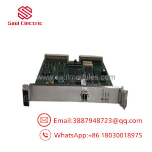
When an αi Power Supply Module (PSM) drops offline on a high-production CNC line, the A20B-2101-0390 power control PCB is typically at the center of the fault trace. Functioning as the primary command card housed inside FANUC A06B-6140 series power supply modules, this board manages overall DC bus charging, soft-start relay execution, and dynamic energy regeneration back to the line grid.
Engineered with an onboard 7-segment LED for instant visual alarm tracking and high-density line noise filtration, the card maintains tight communication across connected αi servo (αiSV) and spindle (αiSP) amplifiers. Replacing a failed command card restores full line excitation without requiring the expense of a complete drive enclosure replacement.
Technical Specifications
- Module Class: Power Control Circuit Board (PCB) for FANUC Alpha i Power Supply Modules (αi PSM / HV αi PSM)
- Host Module Compatibility: FANUC A06B-6140 series high-voltage and standard 200V/400V power modules
- Diagnostics: Onboard 7-segment LED status display for direct fault code readout
- Noise Mitigation: Integrated onboard EMI/RFI noise filter section for clean signal integrity
- Cooling Interface: Integrated mounting pathways designed for panel air-fan ducting (compatible with A90L-0001-0441 fan assemblies)
- System Integration: Multi-pin plug-in headers for connection to the main power wiring PCB and gating drive circuits
- Protection Circuits: DC bus overvoltage detection, control voltage monitoring, and phase loss detection
- Operating Ambient: 0°C to 45°C (32°F to 113°F)
- Weight: Approx. 1.0 kg (2.2 lbs)
Field Application & The “Trench” Experience
During an overnight run at an aerospace machining facility, a 5-axis gantry mill threw a persistent “Alm 04” (DC Bus Overcurrent/Pre-charge Failure) on the primary αi PSM-30 module. The machine operator attempted a warm reboot, but the 7-segment LED on the A20B-2101-0390 remained unlit while the main contactor refused to drop in. A field technician pulled the front cover, swapped out the suspect control PCB with a bench-tested replacement, verified the internal Daito ribbon fuses, and powered the rack up. The 7-segment display immediately initialized to 0 (Ready), allowing the shop to finish a time-critical turbine disk cut with zero scrapped material.
Niche Application Scenarios:
- High-Speed Automotive CNC Transfer Lines: Regulating continuous regenerated DC bus power from high-duty-cycle servo axes during rapid deceleration.
- Large Gantry Mill Spindle Control: Synchronizing line excitation and power management between αi drive stacks and multi-axis spindle amplifiers (αiSP).
- Precision CNC Grinding Cells: Suppressing high-frequency line harmonics via onboard noise filtration to protect sensitive analog feedback encoders.
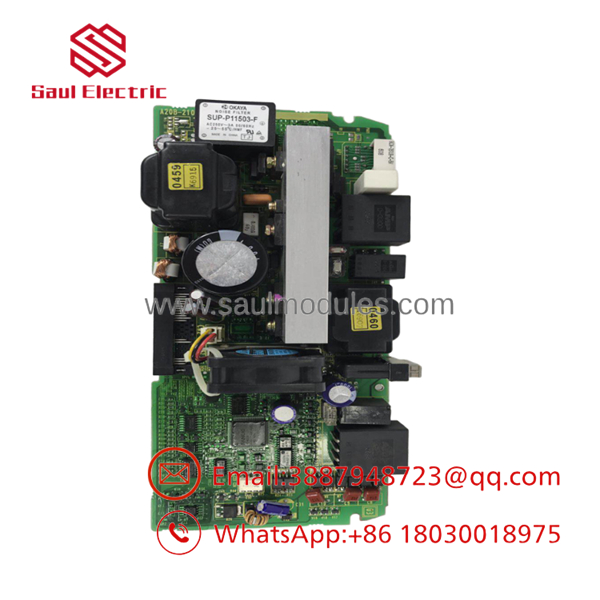
- A20B-2101-0390
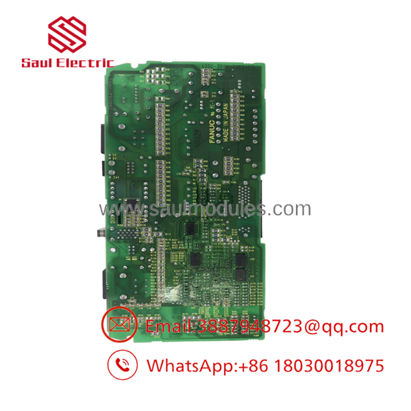
- A20B-2101-0390
Transparency SOP: QA & Testing
To ensure seamless installation, all A20B-2101-0390 control PCBs undergo a rigorous six-stage refurbishment and test cycle:
- Microscopic Visual Inspection: Traces, surface-mount components, and solder joints are inspected under 10x magnification for thermal degradation or micro-cracking.
- Fuse & Passive Component Audit: Daito alarm fuses, SMDs, and onboard power capacitors are measured for nominal capacitance and low ESR.
- Power-Rail Pre-Test: Static resistance measurements are taken across all internal secondary power rails before applying high voltage.
- Mock Module Bench Test: The PCB is installed into a dedicated FANUC A06B-6140 test module on a live CNC simulator rack.
- Full Dynamic Cycling: The test module drives loaded αi Servo and Spindle motors to verify closed-loop power delivery, soft-start contactor control, and regeneration cycles.
- Fault Injection Verification: Alarm states (phase loss, overvoltage, fan failure) are deliberately injected to ensure the 7-segment LED reports the correct diagnostic codes instantly.
The Veteran’s Tech Trap Guide
⚠️ Inspect the Daito Fuses First: Before declaring the A20B-2101-0390 dead, check the tiny green/black Daito surface fuses (such as LM32 / HM32 types) located near the edge connectors. A shorted external 24V supply wire often blows these onboard micro-fuses, cutting power to the 7-segment LED and mimicking a total board failure.
PRO TIP: Mind the wiring PCB interface connectors! When seating this control card into the power supply frame, ensure the pin headers line up perfectly with the underlying wiring board (A16B series). Misaligned pins during forceful installation will bend internal connectors and short out the IGBT gating drives.
⚠️ Check the Cooling Fan Header: The interfaces with the module’s main internal cooling fan. If the fan fails or its connector locks up with metallic chip dust, the board will throw an immediate thermal fault (often display code 1 or 2) and inhibit the CNC ready state until the fan circuit is cleared.
Dynamic FAQ
A: You can replace the PCB individually if the main power components (IGBTs, diode bridges, pre-charge relays) in the chassis are fully functional. However, if an IGBT shorted violently, it may have sent high voltage back into the gating lines of the control PCB, requiring both to be serviced.
Q: What does it mean if the 7-segment display on the board shows no light at all? A: A completely unlit display indicates a loss of 24V control power, a blown onboard micro-fuse, or a total power supply circuit failure on the PCB. Check incoming 24V supply lines and onboard Daito fuses prior to swapping the card.
Q: Is parameter flashing or software installation required after replacing this board? A: No. The is a hardware control board. It does not store machine-specific parameter files; those reside in the CNC main CPU. Once physically installed with matching hardware jumpers, it is ready to operate immediately.
Q: Are these units supplied as new or refurbished?A: Due to legacy production cycles, these cards are typically supplied as fully tested New Surplus or Refurbished/Exchange units. All units are bench-tested on full FANUC simulator rigs prior to dispatch.
Q: What warranty is included with this control board? A: We provide a standard 1-year replacement warranty covering all electronic components and functional execution under normal operating conditions.

 Start Chat


