





Description
Key Technical Specifications
| Parameter | Value |
| Manufacturer | General Electric (GE) |
| Part Number | IS200EGPAG1BCA |
| Board Functional Acronym | EGPA |
| System Compatibility | EX2100 Excitation Control System / Mark VI Speedtronic |
| Primary Function | Dynamic field ground protection sensing |
| Revision Level | G1BCA (Group 1, Backward Compatible Artwork Revision) |
| I/O Interface | High-density terminal headers and rack backplane connectors |
| Isolation Rating | High-voltage galvanic isolation for generator field monitoring |
| Operating Temperature | 0 to +60°C |
| Mounting Orientation | Vertical card rack installation |
Product Introduction
The GE IS200EGPAG1BCA is a specialized Ground Protection Application Board (EGPA) designed for the EX2100 Excitation Control System and Mark VI turbine control platforms. It monitors the insulation resistance of the generator’s main field winding to detect early-stage ground faults, protecting the generator from devastating rotor damage caused by unbalanced magnetic forces.
This board continuously measures leakage currents and processes raw diagnostic telemetry before transmitting data back to the main control processors. By utilizing high-galvanic isolation, the IS200EGPAG1BCA safely interfaces directly with the high-voltage excitation field loops while keeping sensitive digital logic isolated from destructive voltage surges.
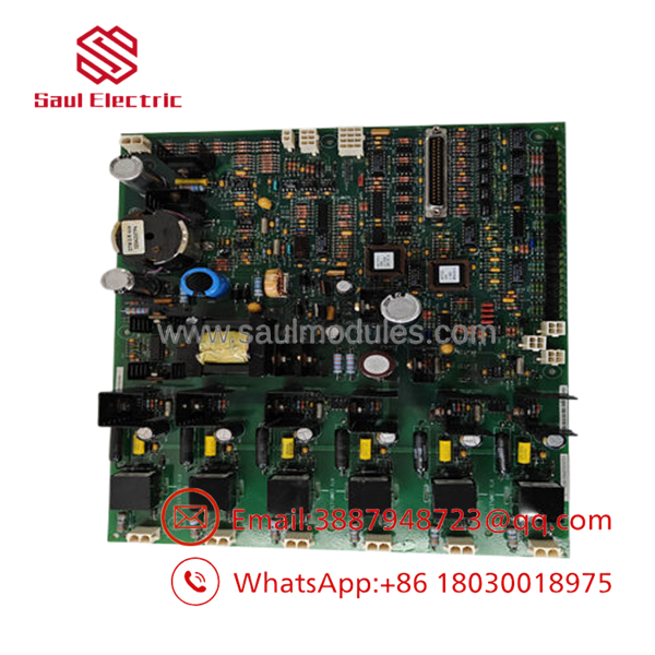
- IS200EGPAG1BCA
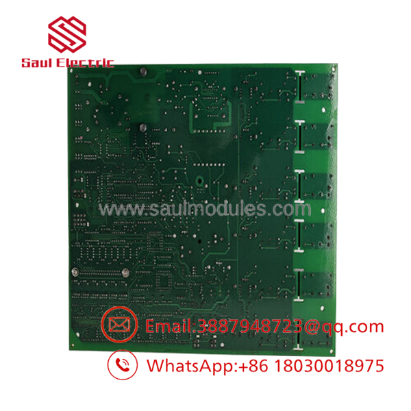
- IS200EGPAG1BCA
Installation & Configuration Guide
Stage 1: Pre-Installation Preparation
- ⚠️ Safety First: Excitation systems handle lethal voltages. Verify that the generator is completely stopped, the field breaker is racked out, and the main bus is locked out and tagged out (LOTO). Wait at least 10 minutes for the excitation system capacitors to fully discharge. Use a high-voltage voltmeter to check for residual DC voltage across the field bus before touching any hardware.
- Tools Required: Grounded ESD wrist strap (mandatory), anti-static mat, flathead terminal screwdriver, 5mm nut driver, and a smartphone for visual reference.
- Data Backup: Document the exact slot location of the old card. Note the layout of any auxiliary ribbon cables connected to the front headers.
Stage 2: Removing the Old Module
- Connect your ESD wrist strap to the designated rack grounding point.
- Carefully disconnect any front-facing ribbon or fiber optic cables from the EGPA board headers, applying pressure only to the connector housing, not the cables themselves.
- Loosen the captive retaining screws located at the top and bottom of the card’s faceplate.
- Grasp the injector/ejector handles firmly, pop them outward to unseat the board from the backplane, and pull the card straight out of the slot tracks.
- ⚠️ Note: Place the pulled card directly into an ESD shielding bag immediately. Do not rest it on bare metal surfaces.
Stage 3: Installing the New Module
- Keep the new IS200EGPAG1BCA inside its ESD bag until the slot is prepped and clear of debris.
- Configuration Clone (Crucial): Compare the hardware layout, onboard jumpers, and hardware revision of the new board against the old unit. Match any physical hardware configuration links exactly as documented from the old card.
- Align the edges of the board with the upper and lower card guides in the rack. Slide the card smoothly inward until the rear connectors approach the backplane pins.
- Press the injector/ejector levers inward simultaneously to fully seat the board into the backplane. Tighten the top and bottom faceplate screws.
- Reattach all front interface cables firmly until the locking tabs snap shut.
- Self-Checklist:
- [ ] Jumpers and hardware link configurations match the removed board exactly.
- [ ] Board is fully seated and faceplate screws are locked down.
- [ ] All front cables are securely plugged into their corresponding headers.
Stage 4: Power-On & Testing
- Re-energize the control power supply rack first, keeping the primary field excitation breaker open.
- Monitor the rack diagnostic LEDs; the status light should stabilize into its normal operating state without throwing a system fault.
- Initialize the ToolboxST or control software to verify that the system recognizes the new board revision without generating a “Card Type Mismatch” error.
- Conduct a dry-run loop test to verify ground path continuity tracking through the software.
- Once clear, close the field breaker and carefully ramp the excitation voltage, watching the ground protection diagnostic dashboard for stability.
- ⚠️ Troubleshooting Note: If the system triggers a diagnostic fault immediately after power-up, verify that the ribbon cable connection is secure and that no backplane pins were bent during insertion.
Frequently Asked Questions (FAQ)
Can I hot-swap this board while the generator is running?
Absolutely not. Pulling the while the excitation loop is live will immediately drop the ground protection loop, causing the master control system to trip the main field breaker. This will result in an instantaneous emergency shutdown (ESD) of the entire turbine-generator unit, alongside high voltage arcing hazards on the backplane.
What do the letters “BCA” mean at the end of the part number?
In the GE Speedtronic and EX2100 numbering ecosystem, “BCA” represents the specific artwork, firmware component assembly, and backward compatibility profile. A board ending in “BCA” is designed to directly replace older revisions of the same group (e.g., G1AAA or G1BBA) without requiring a complete control system software migration or re-flashing.
Will I lose my excitation tuning parameters or system logic when replacing this board?
No. The acts as an application and signal conditioning interface board; it does not host the core control loop software or primary system configuration files. Those are stored securely in the main control processors (such as the UCVE or UCCx cards). However, any hardware jumper selections on the board itself must be matched manually.
Why is your price lower than standard factory list prices for new GE parts?
We procure original legacy control components through verified industrial surplus streams, industrial project cancellations, and insurance spares inventories. By bypassing the standard OEM layer for hard-to-find legacy parts, we pass these capital savings directly to you, maintaining rapid field operations without factory lead-time bottlenecks.
How do you verify that this board is functional before shipping?
Every board goes through a rigorous inspection process. This includes an initial anti-counterfeit visual audit, a complete insulation test, and functional parameter validation within a dedicated testing rack environment. This ensures the high-voltage isolation circuits perform correctly up to factory thresholds before packaging.




 Start Chat


