





Description
Key Technical Specifications
| Parameter | Value |
|---|---|
| Manufacturer | GE Fanuc |
| Model Number | BK698CPA15B0 |
| Product Type | VME64 Controller Module |
| System Architecture | VME64 |
| Input Voltage | 24 V DC |
| Rated Current | Approximately 0.5 A |
| Communication Interfaces | RS-232, RS-485 |
| Operating Temperature | -40 °C to +85 °C |
| Storage Temperature | -55 °C to +85 °C |
| Mounting | VME64 Rack Installation |
| Approximate Dimensions | 100 × 150 × 50 mm |
| Approximate Weight | 0.3 kg |
Product Introduction
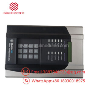
The GE BK698CPA15B0 is a VME64 controller module used in GE Fanuc industrial automation platforms for machine control, process automation, and system communication. It provides controller functionality and interfaces with field I/O and supervisory control systems through standard industrial communication ports.
In field service, these modules are typically purchased to maintain existing installations where redesigning the control platform would be costly. Before installation, verify the rack type, hardware revision, firmware level, and application compatibility because multiple hardware variants may exist under similar part numbers.
Troubleshooting Quick Reference
| Symptom | Possible Cause | Relevance to this Part | Quick Check Method | Recommendation |
|---|---|---|---|---|
| No LEDs after power-up | Missing 24 V DC supply | ❌ Low | Measure the backplane supply voltage with a calibrated multimeter | Verify rack power before replacing the module |
| Controller not detected | Module not fully seated | ✅ High | Remove and reinstall the board while power is OFF | Inspect connectors for bent pins |
| Communication timeout | Firmware revision mismatch | ✅ High | Compare firmware revision with the existing controller | Install a compatible firmware version |
| Serial communication failure | Incorrect baud rate or address | ✅ High | Verify RS-232/RS-485 settings against project documentation | Correct configuration before replacing hardware |
| System boots but application will not run | Corrupted configuration | ✅ Medium | Restore the last verified project backup | Reload configuration and restart |
| Intermittent faults | Backplane connector contamination | ✅ Medium | Inspect edge connectors for oxidation or damage | Clean contacts using approved procedures |
| Overtemperature alarm | Poor cabinet ventilation | ❌ Low | Measure cabinet temperature and inspect airflow | Improve cooling before replacing the controller |
Technical Note: The controller itself is not usually the first component to fail. Power supply issues, backplane faults, firmware incompatibility, and communication settings account for many reported failures. If troubleshooting reaches a dead end, provide photos of the module label, LED status, diagnostic messages, and system logs before ordering a replacement.
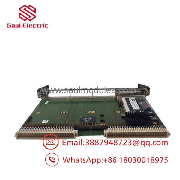
- BK698CPA15B0
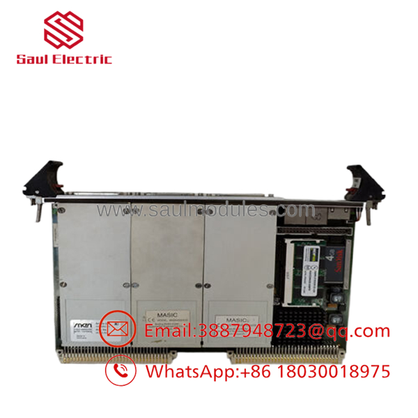
- BK698CPA15B0
Frequently Asked Questions (FAQ)
Q1. Is the GE BK698CPA15B0 still manufactured?
No. It is considered a legacy industrial automation product. Most available inventory consists of New Surplus or professionally tested surplus modules.
Q2. Is this an original GE Fanuc module?
A genuine unit should include the original GE Fanuc identification label, serial number, and matching part number. Request detailed photographs before purchase if traceability is required.
Q3. Can I hot-swap this controller?
Generally, no.
Most VME64 controller installations require system shutdown before removing or installing the module. Removing a controller from an energized rack can interrupt the entire control system and may damage the backplane.
Q4. Will my application automatically transfer to the replacement module?
No.
Back up the controller program, firmware information, and hardware configuration before replacing the module. Restoring the original configuration reduces commissioning time and minimizes startup issues.
Q5. Why is New Surplus inventory less expensive than factory-direct supply?
New Surplus inventory usually comes from canceled projects, OEM excess inventory, or unused maintenance stock. The hardware has not been used in production but is no longer part of the manufacturer’s standard production program.
Q6. What should I verify before ordering?
Verify:
- Exact model number (BK698CPA15B0)
- Hardware revision
- Firmware version
- VME64 rack compatibility
- Communication settings
- Power supply capacity
- Application software compatibility
Five minutes spent verifying these items can prevent hours of troubleshooting during commissioning.
Q7. What warranty is typically available?
Most industrial automation suppliers provide a 12-month warranty for verified New Surplus or fully tested modules. Request a functional test report before shipment whenever possible.
Quality Inspection & Testing SOP
1. Inbound Inspection & Traceability
- Verify OEM labels, serial numbers, and manufacturing markings.
- Inspect the PCB for corrosion, scratches, rework marks, or UV discoloration.
- Check edge connectors for wear or damage.
- Record serial numbers for complete traceability.
2. Live Functional Testing
- Install the module in an in-house -compatible GE test rack.
- Verify normal power-up and LED sequence.
- Test RS-232 and RS-485 communication.
- Confirm controller recognition by the host system.
- Perform continuous operation for more than 24 hours while monitoring temperature.
- Generate a documented functional test report.
- Test photos and videos are available upon request.
3. Electrical Parameter Testing
- Perform insulation resistance testing where applicable using a 500 V Megger.
- Verify ground continuity.
- Measure supply voltage and operating current with a calibrated Fluke digital multimeter.
- Confirm stable operation throughout the test cycle.
4. Firmware & Configuration Verification
- Record the installed firmware revision.
- Document jumper and DIP switch positions with photographs.
- Verify hardware revision against the customer’s requirement.
5. Final QC & Packaging
- Final inspection approval by a QC technician.
- Seal the module in an ESD-safe bag.
- Protect with bubble wrap and heavy-duty corrugated packaging.
- Apply a dated QC Passed label.
Technical Pitfalls & Survival Guide
❗ Firmware Revision Mismatch
I’ve seen a replacement controller spend two days on the bench because the firmware revision differed from the original system. The hardware was fine—the software wasn’t.
Always record the existing firmware before removing the original module.
❗ DIP Switch and Jumper Settings
Take a clear photo before touching anything.
Factory defaults rarely match an operating plant. One incorrect address switch can stop an entire rack from communicating.
❗ Backplane Compatibility
Don’t assume every board is interchangeable.
Verify the rack model, connector arrangement, and supported hardware revision before installation.
❗ Power Supply Capacity
Measure the rack power supply under load and maintain at least a 20% capacity margin. Low supply voltage often appears as random communication faults rather than obvious power problems.
❗ Electrostatic Discharge (ESD)
Always wear a grounded wrist strap.
I’ve watched an expensive controller fail immediately after installation because it was handled on a dry winter day without ESD protection. It looked perfect, but it never completed the boot sequence.
Keep these checks in mind and you’ll avoid most installation mistakes, unnecessary controller replacements, and extended production downtime.


 Start Chat


