





Description
Key Technical Specifications
| Parameter | Value |
| Manufacturer | General Electric (GE) |
| Part Number | IS200VAICH1D |
| Functional Acronym | VAIC |
| Revision Level | D (Latest functional iteration with updated sensor libraries) |
| Analog Inputs | 20 Channels (supports ±5 V DC, ±10 V DC, 4-20 mA, ±1 mA via terminal jumpers) |
| Analog Outputs | 4 Channels (2 channels dedicated 4-20 mA; 2 channels configurable for 4-20 mA or 0-200 mA) |
| A/D Processing | 32-bit floating-point format with advanced digital filtering |
| Scan Rate | 200 Hz |
| System Compatibility | Mark VI Speedtronic VME Rack Ecosystem |
| Terminal Board Match | Dedicated interface with TBAIH1C terminal boards |
| Front Panel Diagnostics | 3 LED Array (RUN – Flashing Green, FAIL – Solid Red, STATUS – Orange) |
| Form Factor | Single-width VME standard assembly |
Product Introduction
The GE IS200VAICH1D is a high-performance VME Analog Input/Output Control Board (VAIC) developed for the Mark VI Speedtronic turbine control matrix. This card handles 20 distinct analog inputs and drives 4 analog outputs, providing real-time processing and engineering unit conversions for vital turbine telemetry, including RTD and thermocouple temperature loops.
Equipped with a 32-bit floating-point processor running at a 200 Hz scan rate, the IS200VAICH1D performs hardware linearization and sensor characteristic checks internally before passing digitized telemetry across the VME backplane. It serves as an upgrade-ready “D” revision asset, featuring updated software curve libraries and optimized electrical stability filters suited for gas, steam, and wind utility drives.
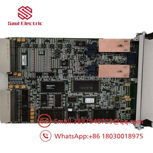
- IS200VAICH1D
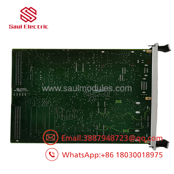
- IS200VAICH1D
Installation & Configuration Guide
Stage 1: Pre-Installation Preparation
- ⚠️ Safety First: The VAIC card interfaces directly with processing loops linked to core governing valves and safety trips. Ensure the turbine management system is placed in an offline engineering or safe maintenance state. Power down the designated VME card rack division before inserting or extracting hardware to prevent backplane bus interruption.
- Tools Required: Grounded anti-static (ESD) wrist strap, ESD protection mat, small flathead screwdriver, and terminal verification reference logs.
- Data Backup: Utilize the Toolbox software to backup the existing I/O channel configuration, scaling profiles, and loop calibrations. Note down the specific terminal matching setup of your peripheral TBAI cards.
Stage 2: Removing the Old Module
- Attach your grounded ESD wrist strap to the designated equipment rack ear.
- Loosen the upper and lower captive retaining screws embedded in the single-width card faceplate.
- Simultaneously pull the top and bottom ejector levers outward to detach the card from the dual 37-pin VME rear backplane slots.
- Smoothly pull the card along the tracking slots out of the rack enclosure.
- ⚠️ Note: Slide the removed board into an ESD shielding pouch instantly to prevent latent component damage from localized static fields.
Stage 3: Installing the New Module
- Retain the new IS200VAICH1D in its static-safe bag until the exact moment of physical installation.
- Configuration Clone (Crucial): Cross-check the board label identifiers. Note that the “D” revision specifically requires matching compatibility with the TBAIH1C terminal board variant. Ensure any jumper settings on the associated terminal blocks are verified to match your loop requirements (e.g., configuring for 4-20 mA vs. voltage).
- Align the edges of the card PCBA with the plastic rack slot channels and push the card slowly inward.
- Firmly actuate the faceplate levers inward to snap the card edge connectors into the backplane pins, then secure the top and bottom captive screws.
- Self-Checklist:
- [ ] Board is seated flush and locked tightly with front-panel levers.
- [ ] Captive chassis screws are snug to ensure frame reference grounding.
- [ ] Associated TBAIH1C terminal jumpers match the intended sensor type (mA/Volt/RTD).
Stage 4: Power-On & Testing
- Restore control voltage to the VME processor rack assembly.
- Monitor the front-panel indicator LEDs during the initialization cycle: the RUN LED should transition to flashing green, and the FAIL indicator must remain dark.
- Access the Toolbox diagnostic environment to check for configuration validation. Verify that the hardware ID device chip on the TBAI terminal board reads successfully without throwing a hardware incompatibility fault.
- Execute real-time data tracing via software to verify that input tracking signals match field parameters.
- ⚠️ Troubleshooting Note: If the STATUS LED flashes orange or a
L3DIAG_VAICerror code triggers, an input has violated its preset hardware operating range limits. Check individual loop current thresholds and terminal wire configurations immediately.
Frequently Asked Questions (FAQ)
Can this board be hot-swapped while the VME rack is fully live?
No. To protect the multi-drop 32-bit VME bus data lines from momentary state corruption or power sags, the VME rack division power switch must be set to off before swapping the . Extracting this card while the system is under live power can lock up the VCMI bus coordinator board, resulting in a complete rack communications failure and an instantaneous turbine safety trip.
What advantages does the “D” revision offer over older “A” or “B” iterations?
The “D” revision stands as the final, highly optimized version of the VAIC product family. It features an upgraded internal sensor characteristic library for more precise linearizations of complex thermal sensor curves. Additionally, component refinements on the PCB trace paths provide improved resistance to high-frequency noise and temperature-induced signal drift across the analog channels.
Is the backward compatible with all TBAI terminal board configurations?
No, it is not. The D-revision variant of this analog control card explicitly relies on integration with the TBAIH1C terminal board generation. Attempting to use this board with older TBAI variants (such as H1A or H1B) will cause the I/O processor to log a hardware type mismatch code during startup because the encoded read-only board ID chip on the terminal panel will fail compatibility validation rules.
How does the board handle signal deviation in Triple Modular Redundant (TMR) setups?
In a TMR configuration, the analog input signals are fanned out from the terminal boards across three parallel VME racks (designated R, S, and T), each holding an individual VAIC card. The processors vote on the values. If an individual channel on one card begins to deviate from the median voted value by a predefined threshold, the system flags a diagnostic warning to notify maintenance teams of an isolated channel drift without interrupting the turbine process loop.
What is the function of the “suicide relays” mentioned in the diagnostic logs for this card?
The analog output control loops on the incorporate dedicated hardware fallback safety switches, colloquially termed “suicide relays.” If the internal system diagnostics identify a catastrophic failure in the D/A conversion circuitry or an un-swappable fault in the drive currents, the processor immediately commands the relay to open. This completely drops the current loop to zero, forcing downstream actuators into their safe baseline states rather than allowing random, erratic output spikes.



 Start Chat


