





Description
Key Technical Specifications
| Parameter | Value |
|---|---|
| Manufacturer | GE (General Electric) |
| Model | IS200VCRCH1B |
| Product Type | Contact Input / Relay Output Board |
| Series | Mark VI Speedtronic |
| Discrete Inputs | 48 Dry Contact Voltage Inputs |
| Relay Outputs | 24 Relay/Solenoid Outputs |
| Input Isolation | 1,500 V |
| System Architecture | Triple Redundant Control Support |
| Rack Interface | VME I/O Rack |
| Associated Terminal Boards | TBCI Contact Input Board, TRLY Relay Output Board |
| Scan Capability | High-speed SOE recording with 1 ms resolution |
| Operating Application | Gas Turbine, Steam Turbine, Generator Control |
The IS200VCRCH1B is installed in the GE Mark VI VME I/O rack and interfaces with TBCI and TRLY terminal boards to process discrete field signals. It supports 48 dry contact inputs and 24 relay outputs for turbine control applications.
Product Introduction
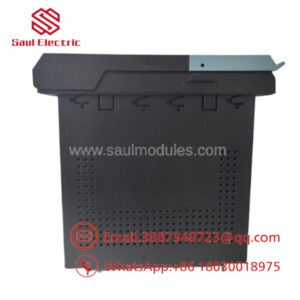
The GE IS200VCRCH1B is a Contact Input / Relay Output Board designed for the GE Mark VI Speedtronic turbine control platform. It acquires discrete field signals from switches, limit contacts, and protection devices while controlling relay and solenoid outputs used in turbine sequencing and auxiliary equipment.
The board provides 48 isolated dry-contact inputs and 24 relay outputs, making it suitable for gas turbines, steam turbines, and generator control systems that require reliable discrete signal processing. Installed in the Mark VI VME rack, it communicates with associated TBCI and TRLY terminal boards while supporting high-speed Sequence of Events (SOE) recording for critical plant diagnostics.
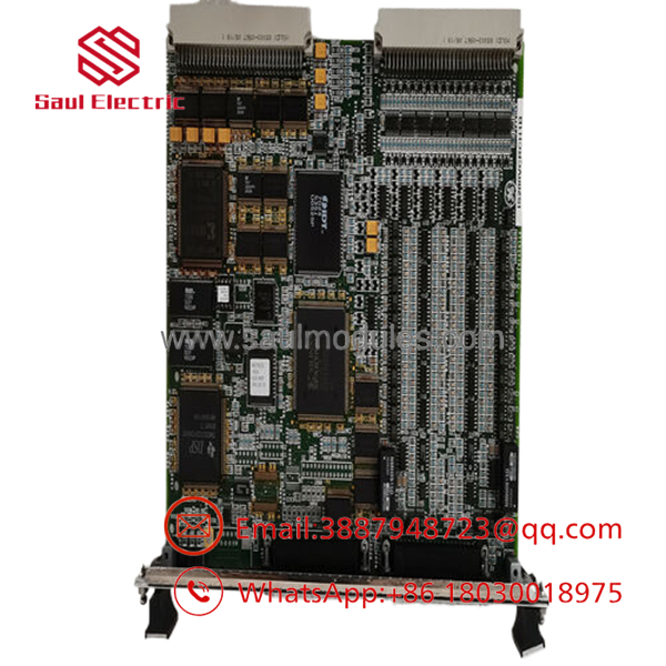
- IS200VCRCH1B
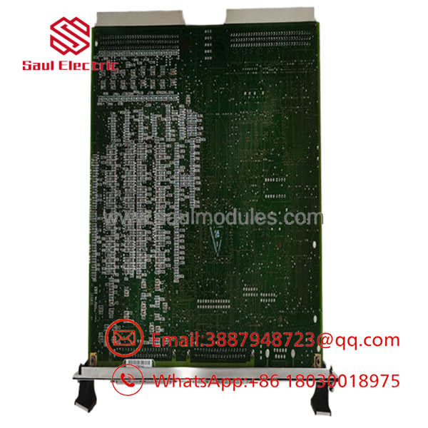
- IS200VCRCH1B
Troubleshooting Quick Reference
| Symptom | Possible Cause | Relevance to this Part | Quick Check Method | Recommendation |
|---|---|---|---|---|
| Multiple contact inputs unavailable | Loss of field power or terminal board fault | ✅ High | Measure control voltage at the TBCI terminal board | Verify field power before replacing the board |
| Relay outputs fail to energize | Relay board or output wiring fault | ✅ High | Measure output voltage and inspect TRLY relays | Check relay board and field wiring |
| Sequence of Events (SOE) not recording | Communication or processor issue | ⚠️ Medium | Review Mark VI diagnostics and SOE logs | Verify controller communication |
| Intermittent contact status | Loose terminal wiring or contact bounce | ⚠️ Medium | Inspect terminals and monitor input transitions | Tighten wiring and inspect field devices |
| Communication loss with I/O rack | Poor VME connector contact | ✅ High | Remove and reseat the board, inspect edge connectors | Clean connectors and verify rack power |
| Entire board offline | Missing rack power or hardware fault | ✅ High | Verify VME rack supply voltages and board LEDs | Confirm power before replacing hardware |
Field Tip: In Mark VI systems, contact input problems are more often caused by field wiring, failed limit switches, blown control fuses, or terminal board issues than by the IS200VCRCH1B itself. Before replacing the board, capture diagnostic logs, inspect the VME connectors, and verify the TBCI/TRLY terminal boards. These checks frequently identify the actual source of the fault.
Frequently Asked Questions (FAQ)
Q1. What is the primary function of the ?
The processes discrete field inputs and controls relay outputs within the GE Mark VI Speedtronic control system. It serves as the interface between field devices and the turbine controller.
Q2. How many I/O channels does this board support?
The board supports 48 dry-contact input channels and 24 relay/solenoid output channels, making it suitable for large discrete I/O applications.
Q3. Which terminal boards are used with this module?
The interfaces with TBCI contact input terminal boards and TRLY relay output terminal boards through dedicated cable connections in the Mark VI VME rack.
Q4. Can this board be replaced while the control cabinet is energized?
No. The board is not designed for hot-swapping. Shut down the control cabinet, follow lockout/tagout procedures, and use appropriate ESD protection before installation.
Q5. Is this product supplied as new or refurbished?
This listing refers to New Original (New Surplus) inventory unless otherwise specified. Each unit should complete visual inspection, electrical verification, connector inspection, and ESD-safe packaging before shipment.
Q6. What inspections should be completed before shipment?
A recommended quality inspection includes:
- OEM part number and serial number verification
- Anti-counterfeit and traceability verification
- Visual inspection for corrosion, repairs, or damaged components
- Power-on verification
- Contact input simulation
- Relay output functional testing
- VME connector inspection
- Final ESD-safe packaging with QC documentation
Test reports and inspection photographs should be available upon request.
Q7. What is the most common installation mistake?
The most common mistake is reconnecting field wiring incorrectly after replacement. Before removing the existing board, photograph every cable and label all connectors. Also inspect the TBCI and TRLY terminal boards, as many reported “board failures” are actually caused by damaged field wiring or terminal board issues rather than the itself.


 Start Chat


