





Description
Product Introduction
The GE Multilin 369-HI-R-M-0-0 is an advanced, microprocessor-based motor management relay designed to safeguard medium-voltage motors across critical processing assets. By continuously analyzing phase currents, ground faults, stator winding temperatures, and bearing thermal dynamics, this unit prevents costly motor burnouts and catastrophic winding insulation failures before they cause unannounced facility shutdowns.
Unlike basic bimetallic overloads or stripped-down digital relays, the 369-HI-R-M-0-0 integrates a thermal model algorithm that factors in current unbalance, ambient temperature, and motor thermal history (hot/cold start ratios). Armed with high control power input (HI), 12 RTD thermal sensor channels (R), and metering capabilities (M), this relay delivers precise microsecond-level trip execution while logging fault waveforms for fast root-cause analysis.
Key Technical Specifications
| Parameter | Value |
| Full Part Number | 369-HI-R-M-0-0 |
| Manufacturer | GE Multilin / General Electric |
| Control Power (HI) | High Range: 50-300V DC / 60-265V AC @ 50/60 Hz |
| RTD Sensing Option (R) | 12 RTD Inputs (100 Ohm Platinum, 120 Ohm Nickel, 10 Ohm Copper configurable) |
| Metering Package (M) | Current, Voltage, Power Factor, kW, kVAR, kWh, Frequency |
| Option Slots (0-0) | Standard Configuration (No additional analog output/Profibus cards) |
| Current Inputs | 1A or 5A secondary CT inputs (Phase and Ground) |
| Relay Outputs | 4 Output Relays (Trip, Alarm, Auxiliary 1, Auxiliary 2) |
| Communication | RS485 Modbus RTU / Front Panel RS232 Port |
| Display & Keypad | 40-character vacuum fluorescent display (VFD) + navigation keypad |
| Operating Temp | -40°C to +60°C (-40°F to +140°F) |
Application Scenarios & The “Trench” Experience
Picture this: It’s 2 AM during a heavy storm, and a 4,160V 2,500 HP raw water intake pump trips off on a phase unbalance alarm. The plant manager is demanding to know if the motor windings are cooked or if the switchgear just saw a transient utility sag. Diagnostics take minutes instead of hours because the 369-HI-R-M-0-0 logs exact thermal capacity used, phase currents at time of trip, and winding temperatures across all 12 RTD points. You don’t have to guess—you can clear the fault, confirm thermal cooling delays, and restart safely.
- Oil & Gas Refineries – High-pressure crude charge pumps – Prevents thermal overload under heavy fluid viscosity surges.
- Mining & Minerals – Semi-autogenous grinding (SAG) mill drives – Monitors stator bearing temperatures across continuous high-impact torque cycles.
- Pulp & Paper Processing – Main digester & refiner motors – Tracks ground faults down to 0.5A to isolate moisture ingress before full short circuits occur.
- Municipal Water & Wastewater – Large centrifugal lift pumps – Eliminates mechanical shock by enforcing minimum restart delay timers and locked-rotor protection.
Field Case Study
A chemical plant in Texas suffered intermittent tripping on a 3,000 HP compressor motor during peak summer months. The original relay was misdiagnosing ambient heat as motor overcurrent due to uncalibrated thermal modeling. We supplied a pre-configured 369-HI-R-M-0-0 relay overnight. The site electrical engineer swapped the drawout chassis, uploaded the setpoint file via GE Enervista software, and verified RTD resistance mapping. The compressor returned to 100% capacity before afternoon thermal peaks without a single false trip.
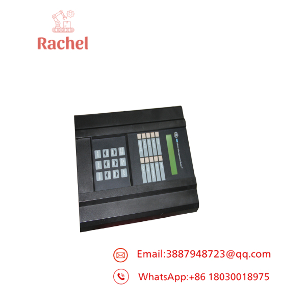
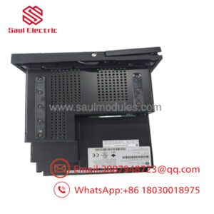
369-HI-R-M-0-0
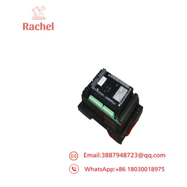
369-HI-R-M-0-0
Transparency SOP: Quality Assurance & Testing
We don’t just ship boxes; we test them on actual GE Multilin secondary injection test rigs:
- Inbound Visual & Hardware Inspection: Inspect faceplate keypads, VFD screen, terminal block screws, and rear connector pins for mechanical stress.
- Power Supply Rail Test: Energize high-voltage power input (HI rail at 120V AC and 250V DC) to confirm power supply stability and low-ripple DC outputs.
- Secondary Injection Current Testing: Inject precise 1A and 5A 3-phase currents via Omicron test set to verify accuracy on phase, neutral, and ground CT input channels.
- RTD Channel Sweep: Connect decade resistance boxes to all 12 RTD terminals to verify temperature accuracy to within ±1°C across Platinum, Nickel, and Copper curves.
- Output Relay Contact Audit: Trigger manual trip/alarm outputs; test contact resistance on NO/NC terminals under 120V load conditions.
- ESD & Protective Packaging: Flash diagnostic logs, wrap unit in static-shielding film, and package inside thick foam shipping cartons.
The Veteran’s Tech Trap Guide
- ⚠️ Check Your Control Voltage (“HI” vs “LO”): The “HI” designation in 369-HI-R-M-0-0 requires 50-300V DC or 60-265V AC. If your control cabinet supplies 24V DC or 48V DC, plugging into this unit will fail to power the relay. Verify your station battery bank voltage before wiring terminal A1/A2.
- ❗ Never Disconnect CTs Under Load: Before pulling the 369 unit or disconnecting rear shorting bars, ensure phase CT secondary circuits are properly shorted. Opening a live CT secondary generates lethal high-voltage arcs that destroy equipment and endanger personnel.
- ⚠️ Verify RTD Shield Grounding: RTD cables must be shielded twisted-pair wire. Ground the shield at the 369 relay end only. Grounding both ends creates ground loops that introduce temperature measurement noise, triggering false stator over-temperature trips.
- ❗ Set the Thermal Capacity Reset Value Correctly: If you set the “Thermal Capacity Used” reset threshold too low after a trip, operators will be blocked from restarting the motor even after it mechanically cools. Match the thermal time constants directly to the motor manufacturer’s cold/hot stall curves.
Frequently Asked Questions
Q: Is the GE Multilin 369-HI-R-M-0-0 a direct replacement for an older Multilin 269 or 169 relay?
A: Yes, structurally and functionally, the 369 was designed as the upgrade path for legacy 269/169 relays. GE manufactured retrofit mounting plates and wire harness adapters to swap physical cut-outs without rewiring the switchgear door from scratch.
Q: Can I configure the 12 RTD inputs for different sensor types on the same unit?
A: Yes. The 12 RTD channels on the “R” option can be individually programmed via the front panel or GE EnerVista software for 100 Ohm Platinum, 120 Ohm Nickel, or 10 Ohm Copper sensors.
Q: What is the purpose of the “M” option on this model?
A: The “M” option adds full power metering capabilities, including line-to-line voltages, real power (kW), reactive power (kVAR), apparent power (kVA), power factor, frequency, and energy consumption (kWh) data.
Q: Does replacing a 369 relay require resetting all motor parameter programming from scratch?
A: No. You can upload the existing .369 setpoint file from your old relay using GE EnerVista software via the front RS232 port, and download it straight into the replacement 369-HI-R-M-0-0 unit within two minutes.
Q: What warranty is provided with this motor protection relay?
A: Every GE Multilin 369-HI-R-M-0-0 unit—whether New Surplus or bench-tested Refurbished—comes with a full 12-month operational warranty covering firmware, metering accuracy, power supply, and contact relay switching.


 Start Chat


