





Description
Key Technical Specifications
| Parameter | Specification Value |
| Processor Architecture | Intel Core 2 Duo operating at 2.16 GHz |
| L2 Memory Cache | 4 Mbyte integrated level-2 cache |
| System/Memory Bus Speed | 667 MHz Front Side Bus (FSB) |
| System Memory (RAM) | Up to 2 Gbyte DDR2 SDRAM via single high-speed SODIMM slot |
| Onboard Storage Interface | Bootable CompactFlash slot up to 8 Gbyte (Secondary IDE path) |
| Core Chipset Deployment | Intel 945GME Express MCH and ICH7-M I/O Controller Hub |
| Backplane Interface | VMEbus Specification VITA 1-1994 compliant (Universe II transparent bridge) |
| Front Panel Network Ports | 2x Gigabit Ethernet ports (RJ45, 10/100/1000 Base-T) |
| Front Panel Connections | 1x SVGA Port, 1x PS/2 Keyboard/Mouse port, 2x USB 2.0, COM1 (RS232/422) |
| Rear I/O Support (via P2) | 2x SATA channels, 2x USB 2.0 loops, COM2 Serial port routing |
| Hardware Expansion Capacity | 1x Local PCI-X PMC site (VITA 35 P2 I/O mapping); Board-to-board link for PMC237 expansion |
| Form Factor Profile | 6U (4HP) single slot Eurocard standard architecture |
| Power Inputs (VME Backplane) | +5 VDC (±5% tolerance), typical operating current matches configuration |
| Operating Temperature | 0 to +55°C (For Core 2 Duo configurations requiring clean airflow) |
Product Introduction
The GE Fanuc V7768-320000 is a full-featured, high-reliability 6U VME single board computer engineered to address demanding real-time processing applications across industrial automation, thermal power unit simulation setups, and critical transportation networks. Operating as a self-contained embedded master node, this single-slot board utilizes the computing performance of an Intel Core 2 Duo 2.16 GHz processor paired with the low-latency Intel 945GME express memory hub. It executes deterministic operations under enterprise-grade real-time operating systems such as VxWorks, Linux, or embedded Windows targets.
The V7768-320000 contains a rich local and distributed I/O array that reduces backplane bandwidth congestion. Featuring front-mounted dual Gigabit Ethernet nodes, legacy PS/2 inputs, and an SVGA display interface, it serves as an excellent direct repair alternative for aging server nodes or standalone process controllers. Additionally, its integrated clear PCI-to-VME bridge (VITA 1-1994 standard) permits it to operate concurrently as either a standalone master controller or a multi-processing peripheral compute module inside legacy modular VME rack enclosures.
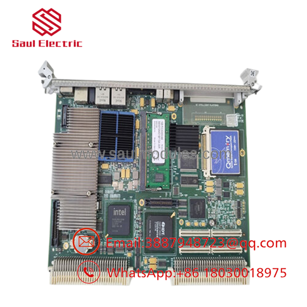
- V7768-320000
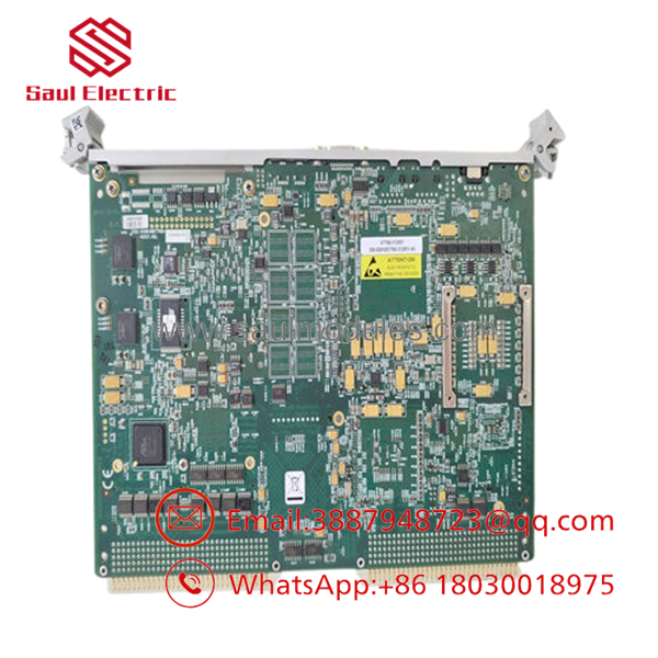
- V7768-320000
Installation & Configuration Guide
Stage 1: Pre-Installation Preparation (Estimated Time: 15 minutes)
- ⚠️ Safety First: Power down the target VME subrack completely. Do not attempt to slide computing cards into energized backplanes; doing so risks cross-pin shorts that can blow the primary Universe II bridging chips on the V7768 or ruin adjacent analog tracking cards.
- Tools Required: Grounded static mat, anti-static ESD wrist strap, small flat-tip screwdriver for card injector handles, and clean compressed air.
- Data Backup: If replacing an operational node, pull the CompactFlash card from the onboard secondary IDE slot or capture a hard snapshot image of your OS drive (VxWorks partition, Linux kernel, or Windows configuration environment) using an external card reader before discarding the board.
Stage 2: Removing the Old Module (Estimated Time: 5 minutes)
- Verify the chassis power status indicators are dark and the ESD wrist band is linked to a chassis bare metal point.
- Unlatch any front panel peripheral cables, including Gigabit Ethernet feeds, serial cables, or USB jumpers. Mark each connector clearly.
- Simultaneously press the upper and lower mechanical injector/ejector handles outward to release the card-edge contacts from the backplane slots.
- Gently guide the older VME board along the card tracks, keeping it horizontal to protect surface-mount components from scratching neighboring assemblies.
Stage 3: Installing the New Module (Estimated Time: 10 minutes)
- Unpack the new surplus V7768-320000 board within your secure ESD-safe workspace.
- Verify that the onboard configuration jumpers and DIP switch blocks exactly reflect your target master or peripheral architecture prints. Ensure the system CompactFlash module is securely locked into its secondary storage holder.
- Carefully line up the 6U Eurocard boundaries with the target slot tracks in the rack chassis.
- Slide the card smoothly back until the front injector hooks catch the lips of the subrack rails. Press the handles inward in a uniform motion to press the P1/P2 connector pins deep into the backplane mother-grid.
- Tighten the upper and lower faceplate thumbscrews to secure the assembly against vibration and establish structural grounding.
❗ Configuration Check:
[ ] Captive front retention hardware handles are locked tightly.
[ ] Core CompactFlash module contains the verified bootstrap image for the system partition.
[ ] Neighboring cards show no mechanical clearance interference issues.
Stage 4: Power-On & Testing (Estimated Time: 15 minutes)
- Re-attach the front network lines, video connectors, and mouse/keyboard links.
- Flip on the primary VME chassis power input.
- Observe the initialization text on the local monitor interface or screen diagnostics output. The system BIOS should pass its standard post checks, map out the 2 GB DDR2 layout, and chain load into your target OS environment (VxWorks bootline prompt or Linux init sequence).
- Check network communication by using a ping routine directed at the front dual Gigabit Ethernet ports from a remote engineering console.
Strategic Quality Control & Inspection Process
To guarantee zero-downtime integration for legacy VME industrial infrastructure, every surplus and reconditioned processing module undergoes a multi-step quality validation protocol.
- Inbound Analysis & Micro-Solder Inspection: We cross-reference manufacturing labels to authenticate build lineage. The single-board multi-layer card undergoes a microscopic inspection to rule out hairline track fissures, connector card pin tracking oxidation, or memory SODIMM clip fatigue.
- Hardware Component Test & Memory Sweep Diagnostics: The module is benched inside a standardized 6U validation rack. We perform thorough RAM hardware verification loops across the entire 2 GB DDR2 architecture, test the boot reliability of the CompactFlash secondary IDE interface, and confirm signaling bounds for all front and rear interfaces (USB, SVGA, Dual GbE).
- Real-Time Operating System Dynamic Load Stressing: The card is loaded with target real-time runtime images (such as VxWorks and Linux test structures). The processing unit runs multi-threaded compute equations for 24 continuous hours while monitoring internal thermal readings to ensure total system processing stability under maximum field limits.
- BIOS Standardization & Clean Master Reset: The operating system system parameters and standard video configurations are reset to baseline reference variables, providing a clean slate for drop-in configuration script additions at the end-user site.
- ESD Sealed Containment Packaging: Following testing clearance, the card ports are fitted with static protection caps. The complete board is wrapped inside heavy anti-static metallized tracking envelopes, shock-isolated with custom dense foam framing, and safely crated for transit alongside its certified technicians’ data evaluation slip.
Frequently Asked Questions
Can this -320000 processing card be pulled or replaced while the VME chassis power is on?
No, it cannot. The classic VMEbus architecture does not inherently support live hot-swapping of core central processor boards unless the chassis is explicitly designed with a highly specific, software-isolated VITA 1.1 hot-swap infrastructure. Pulling the board under load will interrupt backplane cycles instantly, potentially corrupting internal memory, causing operating system crashes across peripheral cards, or physically frying backplane line drivers via power arcing. Always kill primary rack power before service.
My application runs a Celeron M processor. Can this Core 2 Duo board drop in as a replacement?
Yes, in almost all scenarios. The Core 2 Duo model functions as a higher-tier computing option over the basic Celeron M version within the same board architecture footprint. It shares the same 945GME chipset foundation and layout boundaries. However, keep in mind that the Core 2 Duo variation operates with a slightly lower maximum upper operating temperature margin (0 to +55°C) than the low-power Celeron M (which supports up to +70°C). Verify that your enclosure has standard active fan tray cooling blocks installed.
How do I configure this card to function as a System Controller vs. a Peripheral CPU?
The card’s role on the VMEbus backplane is managed dynamically through internal configuration registers accessible via the system BIOS setup layout during initialization. When positioned in Slot 1 of your subrack, it must be configured as the “System Controller” to manage bus arbitration, timing lines, and reset sequences for the rest of the chassis. For installation in slots 2 through 21, toggle the setting to “Peripheral Module” mode to avoid arbitration hardware conflicts with your master card.
Will my existing custom real-world I/O cards connect directly to this processor?
The -320000 provides a flexible local expansion path via its integrated PCI-X PMC (PCI Mezzanine Card) site, which handles custom input/output configurations mapped out to the rear P2 connector via VITA 35 specifications. If your application relies on extensive specialized I/O arrays, you can also link the board-to-board expansion connector to a secondary PMC237 expansion card from Abaco/GE, which introduces three additional PMC modular slots inside adjacent rack boundaries.
Why source a new surplus module instead of upgrading to a current generation processing chassis?
Migrating a legacy operational plant infrastructure or high-fidelity simulation engine away from the VMEbus architecture requires a massive capital investment. It demands completely rewriting embedded application code, modifying physical cabinet routing, updating obsolete documentation sets, and performing exhaustive safety recertifications. Sourcing a new surplus -320000 allows you to drop the exact same architectural fit back into place in under 30 minutes, preserving your original operational software investments while getting lines back online immediately. Every single processing module includes our 1-year independent depot replacement warranty.


 Start Chat


