





Description
Key Technical Specifications
| Parameter | Specification / Value |
| Control Power Input | 60–265 VAC (50/60 Hz), 50–300 VDC |
| Power Consumption | Maximum 20 VA |
| Phase Current Inputs | 1 A and 5 A secondary (field selectable) |
| Ground Current Input | 50:0.025 or 1 A / 5 A secondary |
| RTD Inputs (Option R) | 12 built-in channels, 3-wire (Pt100, Ni100, Ni120, Cu10) |
| RTD Sensing Current | 3 mA |
| Metering Package (Option M) | Voltage, kW, kVar, MVar, Power Factor, Frequency, MWh |
| Analog Outputs | 4 programmable outputs (0–1 mA, 0–20 mA, or 4–20 mA) |
| Output Relays | 4 programmable (Trip, Alarm, Aux 1, Aux 2) |
| Communications | 1 x Front RS232, 3 x Rear RS485 (Modbus RTU up to 19,200 bps) |
| Faceplate Hardware (Option E) | Enhanced Faceplate with high-visibility 40-character LCD |
| Operating Temperature | −40 to +60°C (−40 to +140°F) |
| Dimensions (W x H x D) | 8.50 x 11.50 x 5.50 inches (Cutout: 7.00 x 11.00 inches) |
| Weight | 3.56 kg (7.85 lbs) |
Product Introduction
The GE Multilin 369-HI-R-M-0-0-0-E is a comprehensive, digital protective relay designed for medium-voltage, three-phase AC motors and their associated mechanical assets. Engineered to minimize downtime and prevent catastrophic windings insulation failure, this specialized unit monitors thermal overload, phase unbalance, ground faults, and real-time temperature tracking across crucial bearings and stator elements.
This specific configuration integrates the High-Voltage Power Option (HI), 12 localized RTD inputs (R), and full metering capabilities (M) that deliver detailed electrical values alongside four configurable analog outputs. Finished with the Enhanced Faceplate (E) modification for clear, high-contrast local reading, this module functions as a direct, drop-in replacement for aging or damaged control components in critical infrastructure applications like down-hole pumping, high-inertia fans, and industrial compressors.
Troubleshooting Quick Reference
| Symptom | Possible Cause | Relevance to this Part | Quick Check Method | Recommendation |
| Blank Display / No Front Panel LEDs | Loss of control power or internal power supply failure. | ⚠️ Medium | Verify voltage across control power terminals using a Fluke 115 multimeter. Confirm input is within 50–300 VDC or 60–265 VAC range. | If supply voltage is verified correct and internal fuses are intact, replace the relay unit. |
| RTD Open/Short Circuit Alarm | Field wiring broken or faulty physical RTD sensor. | ❌ Low | Disconnect the specific RTD terminal block. Measure resistance directly across the 3-wire sensor leads and compare against standard curves. | Fix the field wiring run or swap out the physical thermal element; the relay hardware is rarely at fault. |
| Serial Comms Timeout (RS485) | Node address mismatch, missing terminating resistors, or mismatched baud rates. | ⚠️ Medium | Check setpoints via front panel. Ensure baud rate is locked to 19,200 bps (or matched to master) and node ID is unique. | Correct software settings. Verify that termination resistors (120 Ω) are placed at the end of the physical bus line. |
| Unexplained Thermal Capacity Trips | Incorrect motor nameplate entry or unbalance calculations. | ⚠️ High | Access actual values to inspect current unbalance levels. Review historical data loggers via EnerVista 369 software. | Re-evaluate settings against the motor datasheet. If phase current reading is inaccurate under balanced loads, the relay requires recalibration. |
| Analog Output Frozen at 0 mA or 4 mA | Loop configuration error or open circuit loop. | ⚠️ Medium | Put the relay into Simulation Mode. Inject a known signal and measure output loop current directly at terminals. | Check outer loop power source and wire integrity. Reconfigure the output range selection (4–20 mA vs 0–20 mA) in setpoints. |
Note: For stuck logic states or complex diagnostic issues, pull the fault records and contact our technical support division with complete system logs and snapshot files.
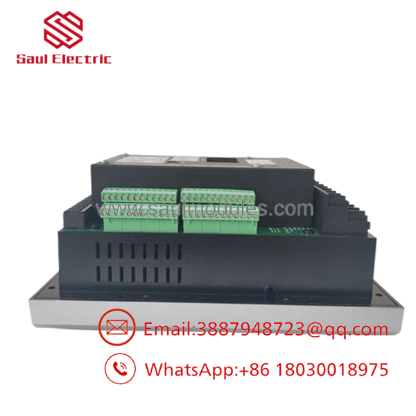
- 369-HI-R-M-0-0-0-E
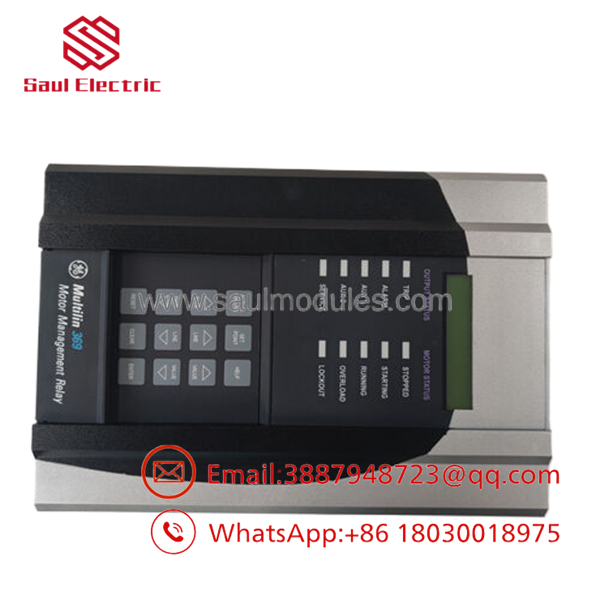
- 369-HI-R-M-0-0-0-E
Frequently Asked Questions (FAQ)
Q: What do the individual codes inside the model number 369-HI-R-M-0-0-0-E represent?
A: This is a fully loaded configuration. HI specifies the high-voltage power supply option, letting you feed the unit 50–300 VDC or 60–265 VAC. R denotes the inclusion of 12 built-in, programmable 3-wire RTD inputs directly on the base card. M indicates the advanced metering package along with 4 analog outputs, adding tracking for power factor, voltage, kW, and frequency. The trailing E confirms this chassis features the Enhanced Faceplate upgrade for improved physical screen readability.
Q: The factory marked this model series as obsolete. How are you providing New Surplus units?
A: While original production runs have ceased at the OEM level, industrial facilities routinely stock critical spares that are never unboxed or put into field operation. We source these clean, unused items directly through plant buybacks, surplus liquidations, and qualified logistics pipelines. Every piece of hardware goes through a full visual validation, electrical check, and physical live test run before arriving at your facility.
Q: Can I swap an old base 369 unit with this “R” and “M” variation without changing my cabinet cutout?
A: Yes, the physical structural dimensions and mounting footprint across the entire 369 series remain identical, meaning the mechanical panel cutout stays exactly 7.00 x 11.00 inches. However, because this specific unit features the 12 RTD inputs and metering hardware options, you must wire the corresponding additional terminal blocks on the rear panel if you intend to execute those functional profiles.
Q: Do I need to apply a firm configuration wipe or firmware flash before replacing my down unit?
A: Never blindly push standard firmwares without checking system parameters. Read and copy the exact setpoint files using EnerVista 369 software from your old device first. Pay close attention to the CT primary/secondary ratios and thermal curves. If your old relay cannot communicate, copy the variables manually step-by-step from the front panel display into your records before unpowering the rack.
Q: Why choose a New Surplus unit over a cheaper third-party repair option?
A: To be blunt, component level repair jobs on safety protection gear can introduce unpredictable points of failure. When an output coil or an isolated logic pathway fails on a repaired card, it risks dropping your entire processing line or failing to trip during a true high-amperage ground fault. A New Surplus item provides unworked, clean factory silicon and pristine traces, minimizing the statistical probability of premature hardware failure out of the box.
Core Strategy Implementation
SOP Quality Transparency & Testing Framework
We eliminate the gamble of surplus supply procurement through an objective, multi-stage testing procedure conducted on every single piece of warehouse stock.
- Traceability Receipt Check: We inspect all intake items for structural deformities, corrosion on copper pathways, or UV panel yellowing. Part numbers and hardware versions are verified against internal traceability lists.
- Live System Bench Testing: Each relay is mounted into an active test enclosure powered by our engineering team using a calibrated power source. We initiate standard power-on self-tests, verify LCD illumination patterns, and observe boot sequences.
- Electrical Multimeter Inspection: Technicians use a Fluke 115 digital multimeter to test grounding continuity across metal framework points. We execute isolation tests on logic loops to confirm zero latent paths.
- Functional Parameter Verification: We upload testing configurations via the front panel RS232 connection to simulate balanced phase currents, step-down CT inputs, and thermal RTD responses. Signal values are tracked through data logs to verify absolute accuracy.
- Anti-Static Packaging Protocol: Following final clearance, configurations are reset to factory defaults. The relay is enclosed inside a heavy-duty ESD protective bag and padded inside reinforced corrugated shipping cartons.
Note: High-definition testing logs, screen snapshots, and functional check videos are recorded for every serial number and are available upon request during order processing.
Technical Pitfall & Survival Guide
Avoid costly installation missteps by reviewing these critical real-world replacement guidelines:
- ❗ Firmware Discrepancies: Ensure your master communications controller can interpret the setpoint arrays of the replacement module. Shifting versions can cause Modbus register addresses to alter slightly, rendering remote DCS configurations unreadable.
- ❗ Nameplate CT Inversion: Always match your current transformer secondary ratings (1 A vs 5 A). Connecting a 5 A secondary circuit into a configuration set for 1 A will cause the module to sense an artificial overcurrent event instantly, locking out the motor line.
- ❗ Terminal Block Tension: Do not use power drivers to cinch terminal screws down into plastic terminal housings. Stripping threads on legacy terminal paths prevents steady wire face contact, generating micro-arcing and false thermal alarms over time.
- ❗ Static Protection: Wire insulation and solid-state internal components are highly vulnerable to voltage spikes. Always clip an ESD grounding wrist strap to the bare enclosure chassis before updating cards or adjusting wiring runs. I once watched an ungrounded field technician handle a premium protection board during a dry winter shutdown; the micro-arc ruined the main processor block instantly on initial powering. Use proper static mitigation gear.



 Start Chat


