





Description
Product Introduction & Engineering Value
Precise timing and motion feedback become increasingly difficult when a control system depends on software-based counting alone. The VMIVME-2540 addresses this challenge by moving high-speed measurement and control functions onto dedicated hardware, significantly reducing the workload on the host processor.
Designed for VMEbus applications, the module combines intelligent firmware with dedicated counter hardware to execute event counting, pulse generation, frequency measurement, and quadrature encoder processing independently. This architecture makes it suitable for demanding real-time automation, motion control, and laboratory measurement systems.
Technical Specifications
| Parameter | Specification |
|---|---|
| Manufacturer | VMIC / GE Fanuc |
| Model | VMIVME-2540 |
| Product Type | Intelligent Counter/Controller |
| Bus Interface | ANSI/IEEE 1014 VMEbus |
| VME Interface | A32/A24, D32/D16/D8 Slave |
| Onboard Processor | Motorola 68HC000, 15 MHz |
| Counter Capacity | Up to 4 Giga Events |
| Measurement Channels | Up to 24 Control/Measurement Interfaces |
| Frequency Measurement | 1.16 × 10⁻³ Hz to 2.5 MHz |
| Pulse Generation | 0.0076 Hz to 2.5 MHz |
| Position Measurement | Quadrature Sin/Cos Inputs up to 1 MHz |
| Input Interface | RS-422 Differential and Single-Ended TTL |
| Memory Window | 64 KB VMEbus Memory |
| Board Format | 6U VME |
Field Application & The “Trench” Experience
An automotive transmission test bench began reporting inconsistent encoder counts during high-speed endurance testing. Engineers initially suspected the encoder itself, but oscilloscope measurements confirmed clean feedback signals. The actual issue was an aging counter/controller board that occasionally missed high-frequency events under peak acquisition rates.
After replacing the VMIVME-2540, the encoder data returned to expected accuracy without requiring modifications to the host software. Continuous measurement mode allowed the onboard processor to acquire data independently, eliminating timing bottlenecks in the VME CPU.
Typical deployment scenarios include:
- Turbine shaft speed and angular position monitoring
- Automated transmission and dynamometer testing
- CNC positioning systems and X-Y motion tables
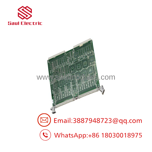
VMIVME-2540
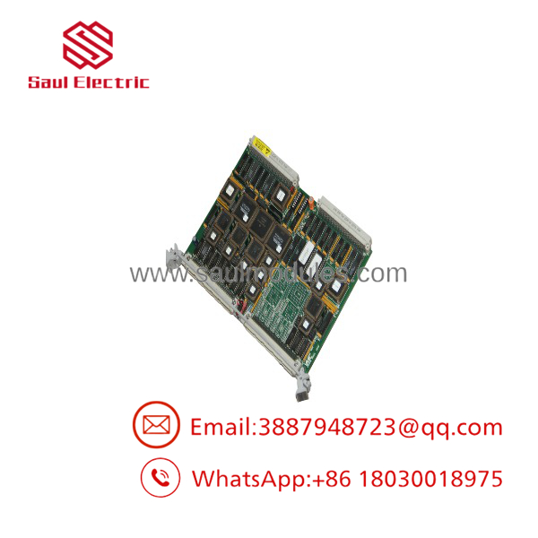
VMIVME-2540
Transparency SOP: QA & Testing
Every VMIVME-2540 undergoes a documented inspection process before shipment.
- Verify the complete model number and PCB revision.
- Inspect VME edge connectors and front-panel I/O connectors for wear or damage.
- Confirm proper boot operation of the onboard 68HC000 processor.
- Validate event counting, pulse generation, and quadrature measurement functions using compatible test fixtures.
- Verify VMEbus communication, interrupt generation, and onboard diagnostics.
- Package the board in ESD-safe materials with reinforced shipping protection.
The Veteran’s Tech Trap Guide
⚠️ Check the Front-Panel Cabling First
Many VMIVME-2540 issues are traced to external breakout cables or terminal blocks rather than the board itself. Damaged RS-422 wiring can produce intermittent counting errors that closely resemble hardware failures.
⚠️ Don’t Ignore Jumper Configuration
The module supports multiple channel configurations and operating modes. Incorrect jumper settings may disable channels or produce unexpected signal behavior after installation.
PRO TIP:
Before replacing the board, verify encoder signal quality with an oscilloscope. Floating differential inputs or improperly terminated RS-422 signals frequently generate false counts that appear to be controller faults.
Dynamic FAQ
Q1. What is the primary function of the VMIVME-2540?
The is a 24-channel intelligent counter/controller that performs event counting, pulse-width measurement, frequency measurement, pulse generation, and quadrature position control for VMEbus systems.
Q2. Does the module require continuous host CPU intervention?
No. Once configured, the onboard 15 MHz Motorola 68HC000 processor executes measurement and control functions independently, reducing host CPU utilization through continuous measurement modes.
Q3. Which input signal types are supported?
The board supports RS-422 differential inputs as well as single-ended TTL signals, making it suitable for a wide variety of industrial sensors and encoders.
Q4. What applications commonly use the ?
Typical applications include motion control, rotary encoder processing, robotics, industrial test systems, laboratory instrumentation, crane positioning, automated storage systems, and machine tools requiring precise timing and measurement.
Q5. How is a New Surplus module verified?
Each New Surplus board is inspected for correct identification, connector integrity, PCB condition, and component authenticity. Functional testing is performed using compatible VME hardware whenever practical.
Q6. Is warranty coverage available?
Yes. Most industrial automation suppliers provide warranty coverage for both New Surplus and professionally refurbished modules. Warranty duration depends on the product condition and supplier policies.



 Start Chat


