





Description
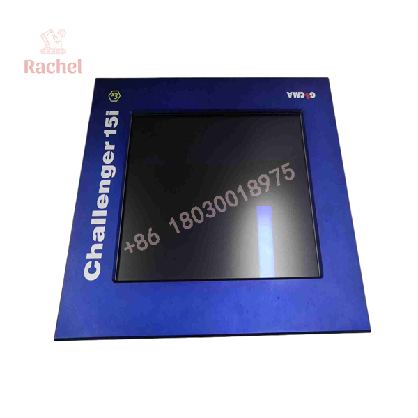
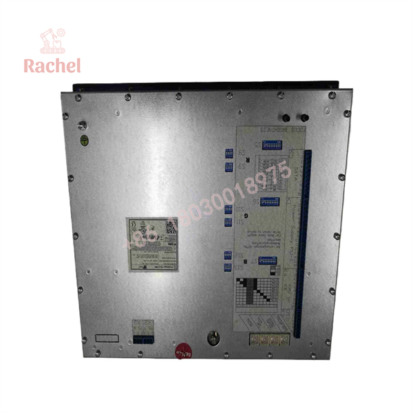
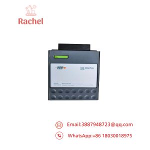
GECMA 15i-2-FMO Display
3. Product Introduction & Engineering Value
Anyone who’s had to run a control room screen fifty feet from a source that could put it inside a Zone 1 area knows the problem: standard monitors just aren’t an option in there. The GECMA Challenger 15i-2-FMO exists specifically to solve that — an intrinsically safe display module built to sit inside the hazardous zone itself while a standard PC does the actual computing safely outside it.
The FMO is the display core of the Challenger 15i-2 terminal, driven remotely over VGA and PS/2 via the TCV2i transmitter — no special graphics card or driver needed on the source PC. Because it’s a defined module within a documented ATEX system, it slots into existing Challenger 15i-2 installations as a like-for-like part, not a redesign.
4. Technical Specifications
Descriptive parameters:
- Protection concept: Intrinsically safe, Ex ia — suitable for Zone 1 and Zone 2 hazardous locations
- Function within system: Remote display core of the Challenger 15i-2 terminal; receives RGB video signal from the TCV2i transmitter
- Video source: Standard IBM-compatible PC via VGA connector (no proprietary card required)
- Companion hardware: TCV2i safe-area transmitter, Challenger KB/KB2D keyboard, M industrial mouse or TB trackball, PSU14i/6/543 or PSU14i/8/543 local power supply
- Max transmission distance (15i-2-FMO): Approximately 600 m from the safe-area PC
- Terminal connections: Connection interfaces at terminal blocks (rigid/flexible conductor, 0.5–2.5 mm²) for ASD (application supporting device) I/O and video input
- Related variant: 15i-2-HB-FMO (high-brightness version, up to 650 cd/m² luminous intensity) — do not substitute without confirming which one your system calls for
- Certified Ex parameters (Ui, Ii, Pi, Ci, Li): Not published in general distribution materials — must be verified against the unit’s nameplate and current ATEX/IECEx certificate before installation
5. Field Application & The “Trench” Experience
Illustrative scenario — not an actual reported incident:
A common integration situation with this module looks like this: a plant is replacing an aging Challenger 15i-2 terminal in a Zone 1 area (say, near a distillation unit) and receives a replacement 15i-2-FMO from a surplus supplier. The tech pulls the old unit, swaps in the new one, and finds no video signal on power-up. The usual culprits in this exact situation: mismatch between the FMO and HB-FMO variant (different luminous intensity spec and possibly different internal parameters), a TCV2i transmitter that’s out of sync with the display’s expected timing, or a barrier/PSU on the safe side that doesn’t match the replacement unit’s IS entity parameters. None of this is a defect in the module itself — it’s a system-matching problem, which is why entity-parameter and variant verification has to happen before power-up, not after.
Specific application scenarios:
- Remote HMI visualization near a Catalytic Cracking Unit Temperature Control panel, where the operator interface must sit inside the classified area but the PC stays in a safe equipment room
- Ethylene compressor station monitoring, where explosion-classification requirements rule out a standard industrial monitor at the point of use
- Offshore platform separator/level control visualization, where cable runs to a safe-area control room exceed what a simple analog VGA extension could reliably carry
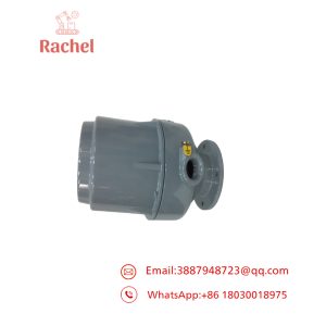
15i-2-FMO
15i-2-FMO
6. Transparency SOP: QA & Testing
Generic pre-shipment verification process we’d recommend for any surplus or refurbished intrinsically safe module like this one:
- Visual and mechanical inspection — enclosure integrity, connector condition, absence of unauthorized modification (critical for Ex-rated equipment, since an opened or altered enclosure can void certification)
- Nameplate and certificate cross-check — confirm the physical unit’s marking matches the documentation being shipped with it, including Ex marking and entity parameters
- Functional bench test — power-up and video signal test using a compatible TCV2i transmitter and safe-area PC to confirm display function
- Documentation packet assembly — datasheet, ATEX/IECEx certificate copy, and test record provided with the unit
(Note: this is a general framework for how such testing should be structured — if you have your own documented QA/SOP process for this stock, that specific language should replace this section.)
7. The Veteran’s Tech Trap Guide
⚠️ Variant mismatch: FMO and HB-FMO are not interchangeable without checking luminous intensity requirements and entity parameters. Grabbing “the closest GECMA display” off a shelf is how you end up with a screen that’s either too dim for the application or, worse, doesn’t match the certified IS loop.
⚠️ Entity parameter matching is non-negotiable. The whole point of intrinsic safety is that every component in the loop — barrier, transmitter, display — has matched Ui/Ii/Pi/Ci/Li values. Swapping in a “compatible-looking” module without confirming these against the system’s current certificate isn’t a shortcut, it’s a certification violation.
PRO TIP: Don’t assume the old unit’s paperwork is still accurate. Systems get modified in the field over the years. Pull the current loop certificate, not the one from the original install binder.
⚠️ ESD and enclosure integrity: These modules are opened at your own risk from a certification standpoint — GECMA specifies the case may only be opened by the manufacturer. Treat any unit with signs of unauthorized disassembly as suspect, full stop.
8. Dynamic FAQ
Q: Is the 15i-2-FMO the same as the 15i-2-HB-FMO?
No — the HB variant is a higher-luminous-intensity version (up to 650 cd/m²). Confirm which one your terminal originally used before ordering a replacement.
Q: What warranty applies to a “New Surplus” 15i-2-FMO?
[Insert your actual warranty terms here — commonly 12 months on refurbished/surplus industrial electronics, but confirm your company’s real policy rather than assuming a standard.]
Q: Can I get the Ex entity parameters (Ui, Ii, Ci, Li) for this specific unit?
These should be confirmed against the physical nameplate and current ATEX/IECEx certificate for the exact serial/revision you’re purchasing — not assumed from general product literature.
Q: What’s the maximum cable distance between the safe-area PC and this display?
Approximately 600 m via the TCV2i transmitter, per GECMA’s published system architecture.
Q: Does this require a special graphics card or driver on the host PC?
No — the system is designed to work with any standard IBM-compatible PC and its onboard VGA output.
Q: Is this unit tested before shipment?
Yes — see the QA/testing section above for the general verification process; ask us for the specific test record for your unit’s serial number.

 Start Chat


