





Description
Core Product Summary
The GMI D5091S is a single-channel SIL 3 relay output module manufactured by G.M. International for switching safety-related circuits in high-risk industries, certified according to IEC 61508:2010 Ed.2 with TÜV functional-safety certification. It takes a 24 Vdc nominal input (21.6–27.6 Vdc, reverse-polarity protected) and provides one voltage-free SPDT relay contact rated 5 A at 250 Vac / 1250 VA or 5 A at 250 Vdc / 140 W for resistive loads.
A distinctive design point is that the one SPDT contact serves two different SIL 3 safety functions for Normally De-energized loads, selectable between an ND relay condition (terminals 7–8) and an NE relay condition (terminals 9–10). The module includes two mutually exclusive, DIP-switch-selectable monitoring circuits — DCS/PLC line input monitoring (pulse test) and driving-voltage monitoring — and provides 2.5 kV input/output isolation. It mounts on a standard EN/IEC 60715 TH 35 DIN-Rail or termination board, is approved for Safe Area or Zone 2 / Class I, Division 2 installation (Group IIC, T4), and carries ATEX, IECEx, INMETRO, NEPSI, UL, C-UL, FM, and DNV/KR maritime approvals.
Key Technical Specifications
| Parameter | Value |
|---|---|
| Product type | Single-channel SIL 3 relay output module (DIN-rail) |
| Manufacturer / series | G.M. International, D5000 relay family |
| Functional safety | SIL 3 according to IEC 61508:2010 Ed.2, low demand mode, Type A, HFT = 0; TÜV certified |
| Input | 24 Vdc nominal (21.6–27.6 Vdc), reverse-polarity protected, ripple ≤ 5 Vpp |
| Current consumption @ 24 V | 35 mA (relay energized, line monitoring off) / 45 mA (line monitoring on), typical |
| Power dissipation | 0.85 W / 1.1 W (line monitoring off/on), typical |
| Output | 1 voltage-free SPDT relay contact (Ag alloy, cadmium-free, gold plated) |
| Contact rating | 5 A 250 Vac / 1250 VA; 5 A 250 Vdc / 140 W (resistive); 1 A 24 Vdc; 220 mA 125 Vdc; 110 mA 250 Vdc (UL); min. switching current 1 mA |
| Contact inrush current | 6 A at 24 Vdc / 250 Vac |
| Operate / release time | 8 ms / 4 ms typical; bounce 3 / 8 ms (NO/NC) |
| Isolation (test voltage) | Input/output 2.5 kV |
| Frequency response | 10 Hz maximum |
| Installation location | Safe Area / Non-Hazardous, or Zone 2 / Class I, Division 2, Group IIC, T4 |
| Operating temperature | −40 to +70 °C (95% RH up to 55 °C); max altitude 2000 m |
| Dimensions / weight | 12.5 × 123 × 120 mm (W × D × H); approx. 125 g |
| Protection class | IP 20 |
| Termination | Polarized plug-in disconnect screw terminal blocks, up to 2.5 mm² |
Engineering Selection Highlights
- Two SIL 3 safety functions on one SPDT contact: Terminals 7–8 provide the SIL 3 function for ND load with ND relay condition; terminals 9–10 provide it for ND load with NE relay condition. PFDavg (1 year) is 1.59 E-05 with SFF 96.35% (ND relay) and 7.01 E-06 with SFF 99.17% (NE relay), so the relay-condition choice affects proof-test interval planning.
- Proof-test interval is application-dependent: Tproof is 6/20 years (ND relay) or 14/20 years (NE relay) depending on whether the function represents ≤10% or >10% of the total SIF — a direct input to the SIF documentation.
- 5 A contact with 6 A inrush tolerance: Suitable for final-element switching of solenoid valves, starters, and similar loads; contact breaking capacity varies with load voltage and must be checked against the manufacturer’s breaking capacity diagram, with external fuse protection required.
- DCS/PLC line monitoring compatibility: The DIP-switch-selectable line input monitoring permits pulse testing by the driving DCS/PLC without relay or LED flickering, widening compatibility across control-system platforms.
- Low-voltage input monitoring: When enabled, the module reflects a high-impedance state (≤ 10 mA) to the control unit when the driving voltage falls below threshold (≥ 21.6 Vdc normal, ≤ 17 Vdc flagged), supporting drive-level fault detection.
- Zone 2 / Division 2 installation scope: Ex nA nC IIC T4 Gc (ATEX/IECEx/INMETRO/NEPSI) and UL/FM NI ratings allow the same module to be used in classified areas without a separate model variant.
- Marine approvals: DNV and KR type-approval certificates cover maritime applications where class-society documentation is required.
Detailed Product Overview
The D5091S is best understood as a certified final-element interface rather than a general-purpose relay. G.M. International designed it for the specific role of switching safety-related circuits at SIL 3 capability in low-demand mode, classified as a Type A module with hardware fault tolerance of zero. The engineering value lies in the details that make that classification usable in a real SIF calculation: documented PFDavg and SFF figures for both relay conditions, defined proof-test intervals tied to the module’s share of the total SIF, and a TÜV-certified functional safety management system behind the product.
The single SPDT contact architecture is unusual and worth attention during design. One physical contact supports two different SIL 3 safety functions: with an ND relay condition, the driving signal is normally 0 Vdc, the relay is de-energized, and the safety action energizes the load by applying 24 Vdc; with an NE relay condition, the driving signal is normally 24 Vdc and the safety action de-energizes the relay. The terminal pair not used for the SIL function (7–8 or 9–10) remains available as a service contact with the opposite, non-SIL behavior. This means a single module order can serve either design philosophy, but the DIP-switch and wiring configuration must match the chosen function exactly, per the safety manual.
On the input side, the two monitoring circuits are mutually exclusive. Line input monitoring exists for DCS/PLC pulse testing: an internal circuit absorbs the test pulses so the relay coil and status LED do not flicker, which keeps the output contact stable while the control system verifies line continuity. Voltage monitoring instead watches the drive level: at 21.6 Vdc and above the module operates normally, while at 17 Vdc and below it presents a high-impedance state (≤ 10 mA) to the control device, a signature the control system can detect and alarm.
The output is a voltage-free contact with Ag-alloy, gold-plated (cadmium-free) contacts rated 5 A at 250 Vac or 250 Vdc resistive, with a 6 A inrush allowance at 24 Vdc / 250 Vac. Because the AC/DC breaking capacity falls as load voltage rises, the installation instructions require external fuse protection selected from the breaking capacity diagram — a step that is easy to omit but is a documented installation requirement.
Installation is deliberately flexible: standard TH 35 DIN-rail mounting with plug-in disconnect terminal blocks, or customized termination boards for pre-wired marshalling. The enclosure is IP 20 and the module is intended for pollution degree 2 environments. The wide −40 to +70 °C operating range and the Zone 2 / Division 2 approval set (ATEX, IECEx, UL, C-UL, FM, INMETRO, NEPSI, EAC-EX, plus DNV/KR marine type approvals) allow one part number to serve both conventional cabinets and classified-area or marine installations, simplifying project standardization.
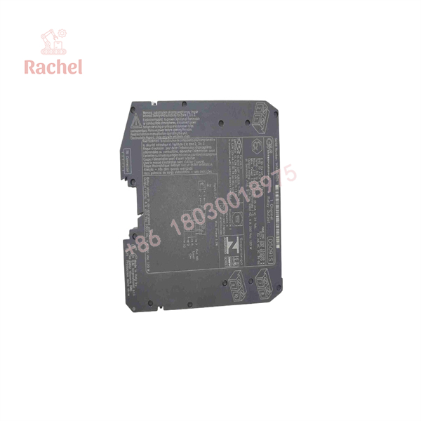
D5091S
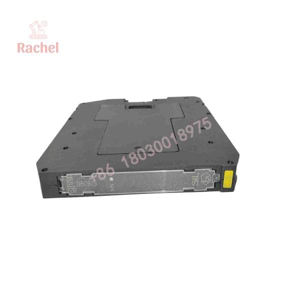
D5091S
System Compatibility & Integration Requirements
| Item / Dependency | Verified Compatibility or Requirement | Practical Note |
|---|---|---|
| Driving signal | 24 Vdc nominal (21.6–27.6 Vdc), reverse-polarity protected | Ripple must stay within limits (≤ 5 Vpp) |
| Safety function 1 | SIL 3, ND load with ND relay — terminals 7–8 | Driving signal normally 0 Vdc; contact closes at 24 Vdc |
| Safety function 2 | SIL 3, ND load with NE relay — terminals 9–10 | Driving signal normally 24 Vdc; contact closes at 0 Vdc |
| Service contact | Opposite (non-SIL) function available on the unused contact pair | For service loads only, not safety duty |
| Mounting | EN/IEC 60715 TH 35 DIN-rail or customized termination board | DIN-rail stopper accessory MCHP196 available |
| Installation location | Safe Area / Zone 2 / Class I Division 2 (IIC T4) | Ambient −40 to +70 °C |
| Monitoring configuration | Line input monitoring and voltage monitoring mutually exclusive, DIP-switch selected | Configure per the safety manual before start-up |
| External protection | Fuse or similar required, per relay breaking capacity diagram | Prevents contact damage on inductive loads |
| EMC | EN 61000-6-2, EN 61000-6-4, EN 61326-1, EN 61326-3-1 (safety system) | Supports installation in industrial EMC environments |
| Repair policy | Unit is not user-repairable; return to manufacturer or authorized representative | Unauthorized modification must be avoided |
Dimensions, Mounting & Connection Notes
- Dimensions: 12.5 mm wide × 123 mm deep × 120 mm high; weight approximately 125 g — a slim half-density housing for crowded safety cabinets.
- Mounting: standard EN/IEC 60715 TH 35 DIN-rail or G.M. International customized termination boards; DIN-rail stopper accessory MCHP196 available.
- Connections: polarized plug-in disconnect screw terminal blocks accommodating wire up to 2.5 mm²; input at terminals 1 (+) and 2 (−), output at terminals 7–10.
- Environment: operating −40 to +70 °C, storage −45 to +80 °C, relative humidity 95% up to 55 °C, maximum altitude 2000 m, IP 20 enclosure (EN 60529), pollution degree 2 per EN/IEC 60664-1.
- Contact protection: connect external protection (fuse or similar) chosen according to the relay breaking capacity diagram in the installation instructions.
Applications & System Role
In a safety instrumented system, the D5091S sits at the final-element interface: it converts a 24 Vdc logic signal from a safety PLC, DCS trip logic, or interlock circuit into a voltage-free relay contact that can switch a process load — for example a solenoid valve, shut-off device, or alarm circuit — while maintaining the isolation and failure-detection properties required for SIL 3 low-demand service. Its input-side monitoring functions are designed for the DCS/PLC environment: line monitoring supports the periodic pulse testing that many control systems perform on output lines, and voltage monitoring reports undervoltage drive conditions back to the control unit as a high-impedance signature.
The Zone 2 / Division 2 approval scope means the module can be mounted inside cabinets located in classified process areas, not only in unclassified control rooms, which is a frequent constraint in oil, gas, and chemical facilities. The DNV and KR maritime type approvals extend the same module to offshore and marine applications. Fit scenarios include SIL-rated emergency shutdown and fire & gas output circuits where a Normally De-energized load must be energized in the fail-safe state, and where proof-test planning is based on the documented PFDavg and SFF figures.
FAQ
What is the GMI D5091S?
It is a single-channel SIL 3 relay output module from G.M. International for switching safety-related circuits up to 5 A, certified according to IEC 61508:2010 Ed.2.
What safety certification does it hold?
SIL 3 capability with TÜV functional-safety certification, plus ATEX, IECEx, INMETRO, NEPSI, UL, C-UL, FM, EAC-EX, and Ukrainian certifications, and DNV/KR type approvals for maritime applications.
What input does it require?
24 Vdc nominal (21.6–27.6 Vdc), reverse-polarity protected, with ripple within limits of ≤ 5 Vpp; typical consumption is 35–45 mA depending on the monitoring configuration.
What is the contact rating?
One voltage-free SPDT contact rated 5 A 250 Vac (1250 VA) or 5 A 250 Vdc (140 W) resistive, with a 6 A inrush allowance at 24 Vdc / 250 Vac and a minimum switching current of 1 mA.
Where can it be installed?
In Safe Area / non-hazardous locations or in Zone 2 / Class I, Division 2 areas (Group IIC, T4), on EN/IEC 60715 TH 35 DIN-rail or a termination board.
What are the two SIL 3 safety functions?
Terminals 7–8 provide the SIL 3 function for an ND load with ND relay condition; terminals 9–10 provide it for an ND load with NE relay condition. The unused pair serves as a non-SIL service contact.
What monitoring functions are built in?
Two mutually exclusive DIP-switch-selectable circuits: line input monitoring for DCS/PLC pulse testing, and driving-voltage monitoring that reflects a high-impedance state to the control unit below the voltage threshold.
What are its physical and environmental limits?
Dimensions 12.5 × 123 × 120 mm at approximately 125 g, IP 20 protection, operating temperature −40 to +70 °C, 95% RH up to 55 °C, and maximum altitude 2000 m.

 Start Chat


