





Description
Core Product Summary
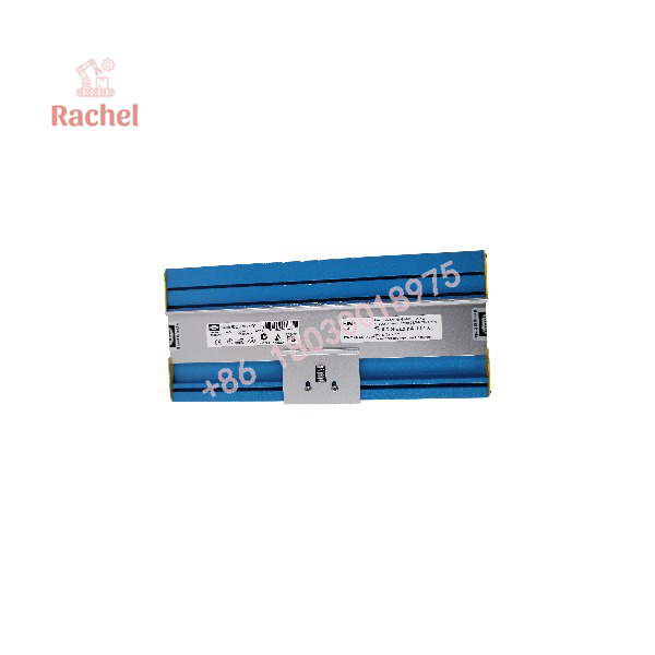
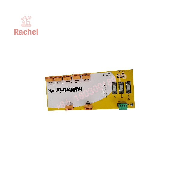
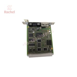
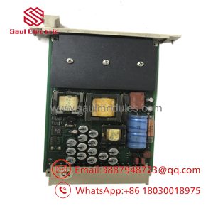
The HIMA F30 03 SILworX 209 is identified for product-page purposes with the HIMatrix F30 03 family of safety-related compact controllers. This controller integrates safety-related digital input and output functions in a metal enclosure and is configured using the SILworX engineering tool. Its primary role is to execute application logic that processes field signals and controls safety-related outputs.
The documented F30 03 hardware provides 20 digital inputs, 8 digital outputs, four RJ-45 Ethernet ports with an integrated switch, and three 9-pin D-sub fieldbus interfaces. Its communication and I/O resources support integration into appropriately engineered safety-control architectures. The exact relationship between the additional suffix 209 and the manufacturer’s hardware designation should be established from the unit’s type label before ordering a replacement.
Key Technical Specifications
| Parameter | Documented F30 03 specification |
|---|---|
| Manufacturer | HIMA |
| Product family | HIMatrix |
| Model designation | F30 03 |
| Engineering environment | SILworX |
| Controller type | Safety-related compact controller |
| Digital inputs | 20, non-galvanically isolated |
| Digital outputs | 8 |
| Program and data memory | 5 MB, less 64 kB for CRCs |
| Response time | ≥ 6 ms |
| Ethernet interfaces | 4 × RJ-45, 10/100Base-T, integrated switch |
| Fieldbus interfaces | 3 × 9-pin D-sub |
| Fieldbus interface details | FB1 and FB2 accept pluggable fieldbus submodules; FB3 provides RS-485 for Modbus master/slave or ComUserTask |
| Supply voltage | 24 VDC, −15% to +20% |
| Maximum current input | 8 A at maximum load |
| Idle current | 0.5 A |
| External fuse | 10 A time-lag fuse |
| Operating temperature | 0°C to +60°C |
| Storage temperature | −40°C to +85°C |
| Protection rating | IP20 |
| Dimensions | 257 × 114 × 66 mm (W × H × D, maximum dimensions including specified hardware features) |
| Approximate weight | 1.2 kg |
| Documented order number | 98 2200496 |
Engineering Selection Highlights
- 20 digital inputs: Provides channels for safety-related field signals. Check the input circuit design, signal voltage, and line-monitoring configuration against the application requirements.
- 8 digital outputs: Supports safety-related output control. Confirm the electrical characteristics of the connected loads and the required output behavior.
- SILworX engineering: The F30 03 variant is designed for configuration using SILworX. Confirm that the available engineering environment and project configuration support the installed hardware.
- Integrated Ethernet switch: Four RJ-45 ports support Ethernet connectivity. Network configuration must account for addressing, routing, and the protocols required by the application.
- Fieldbus connectivity: Three D-sub interfaces provide fieldbus integration options, including configurable submodule arrangements on FB1 and FB2 and RS-485 functionality on FB3.
- 24 VDC supply: The controller requires a suitable supply within its specified voltage range. Power sizing must account for connected loads and maximum current demand.
- Safety certification scope: The documented F30 03 family has safety-related application certifications. The required certification level must be assessed against the exact application, hardware revision, firmware, and system configuration.
F30 03 SILworX 209
F30 03 SILworX 209
System Compatibility & Integration Requirements
| Item / dependency | Documented requirement | Practical note |
|---|---|---|
| Engineering software | SILworX | Use a compatible engineering environment and the appropriate project configuration. |
| Power supply | 24 VDC, −15% to +20% | Check supply capacity, wiring, and protective devices. |
| Ethernet | Four RJ-45 ports with integrated switch | Configure IP addressing and network parameters for the intended architecture. |
| Fieldbus | Three 9-pin D-sub interfaces | Confirm the required submodules and communication configuration for FB1 and FB2. |
| RS-485 | Available on FB3 | The documented options include Modbus master/slave or ComUserTask. |
| Field wiring | Safety-related digital inputs and outputs | Follow the applicable wiring diagrams and safety manual, including the prescribed fault-response behavior. |
Additional suffix 209 |
Exact suffix-to-hardware relationship not established | Compare the complete type label, part number, hardware revision, and firmware revision before substitution. |
Dimensions, Mounting & Connection Notes
The documented F30 03 controller has maximum dimensions of 257 mm wide, 114 mm high, and 66 mm deep, with an approximate weight of 1.2 kg. These dimensions include the specified housing screws, fixing bolt, and earthing screw.
The controller is intended for installation in a suitable control enclosure or system environment. Its documented protection rating is IP20, so enclosure design must provide the environmental protection required at the installation site.
Installation and commissioning should account for the following:
- Provide a 24 VDC supply within the specified operating range.
- Observe electrostatic-discharge precautions when handling or replacing the controller.
- Keep ventilation openings unobstructed.
- Follow the manufacturer’s terminal assignments and wiring requirements for the digital inputs and outputs.
- Configure the controller using SILworX and verify the loaded application before placing the system into operation.
Detailed Product Overview
Controller architecture and digital I/O
The HIMA HIMatrix F30 03 combines a safety-related processor system, communication system, digital inputs, and digital outputs in a compact metal enclosure. This integrated design places the logic-processing and field-interface functions within one controller.
The 20 digital inputs receive discrete field signals. Individual input status indicators assist with local diagnosis, while configured fault handling determines how abnormal input conditions are processed by the application. The 8 digital outputs provide the controller’s discrete output interface for the intended control function.
The input and output channels must be assessed against the actual field circuit. Signal voltage, wiring arrangement, load characteristics, and the required safe state all influence whether the controller is suitable for a particular installation.
Communication and engineering configuration
Four RJ-45 Ethernet ports with an integrated switch provide the controller’s Ethernet connections. Three 9-pin D-sub interfaces provide fieldbus connections. Two of these interfaces accept pluggable fieldbus submodules, while the third provides RS-485 communication for Modbus master/slave or ComUserTask.
These interfaces do not, by themselves, establish compatibility with every network or controller architecture. The engineering configuration must match the selected protocol, network topology, addressing scheme, and connected equipment.
SILworX is the documented programming environment for the F30 03 variant. Configuration includes the controller’s processor and communication functions as well as its input and output channels. The selected engineering project must correspond to the actual installed hardware and its supported operating system.
Power and environmental requirements
The controller operates from a nominal 24 VDC supply, with a documented tolerance of −15% to +20%. Maximum current input is specified as 8 A under maximum load, with an idle current of 0.5 A. The documented external protection requirement is a 10 A time-lag fuse.
The specified operating temperature range is 0°C to +60°C, and the storage range is −40°C to +85°C. The IP20 rating should be considered when designing the control cabinet and determining the necessary protection against dust, moisture, and physical contact.
Safety configuration and maintenance
The F30 03 is intended for safety-related control applications. Its documented certification scope includes SIL 3 under specified functional-safety standards and PL e under EN ISO 13849-1. The applicable safety level for a particular installation must be established through the complete system design and the relevant certification documentation.
During commissioning and maintenance, diagnostic LEDs and the engineering tool can help identify operating states and faults. Any replacement or reconfiguration should preserve the validated safety application, correct hardware identification, wiring arrangement, and approved engineering settings.
For procurement, the most important identification step is to compare the full product label with the order designation. In particular, the suffix 209 should not be treated as a confirmed hardware revision or standalone model variant without supporting identification information.
Applications & System Role
The HIMatrix F30 03 is a safety-related programmable controller that processes digital field signals and executes configured application logic. Within an automation architecture, it can serve as a local safety-control unit between field devices and the equipment controlled by its digital outputs.
Its 20 inputs and 8 outputs provide the basic I/O resources for applications that use discrete signals. The Ethernet interfaces provide network connectivity, while the fieldbus interfaces support additional communication options determined by the selected submodules and configuration.
The controller’s safety function depends on more than its hardware. The application program, signal wiring, fault handling, engineering configuration, and overall system design must be suitable for the required safety function. Input line monitoring can be configured to detect certain wiring faults, including short circuits and open circuits, when the prescribed wiring and configuration methods are used.
The F30 03 also supports sequence-of-events recording, multitasking, and reload functionality. The manufacturer documentation specifies that a license is required to use these features. Their availability should therefore be considered during project planning rather than assumed from the hardware designation alone.
FAQ
What is the HIMA F30 03 SILworX 209?
It is a supplied product designation associated with the HIMA HIMatrix F30 03 safety-controller family. The documented F30 03 is a compact safety-related controller with 20 digital inputs and 8 digital outputs. The additional 209 suffix requires confirmation against the unit label.
Which programming software does the F30 03 use?
The documented F30 03 variant is configured using SILworX. The engineering project and software environment must support the installed controller hardware and operating system.
How many digital inputs and outputs does the controller have?
The documented F30 03 has 20 digital inputs and 8 digital outputs.
What power supply does the F30 03 require?
It operates on 24 VDC, with a specified tolerance of −15% to +20%. The installation must also account for the controller’s current demand and required external fuse.
Which communication interfaces are available?
The documented hardware has four RJ-45 Ethernet ports with an integrated switch and three 9-pin D-sub fieldbus interfaces. FB1 and FB2 accept pluggable fieldbus submodules, while FB3 supports RS-485 for Modbus master/slave or ComUserTask.
What is the operating temperature range?
The documented operating temperature range is 0°C to +60°C. The specified storage temperature range is −40°C to +85°C.
What should be checked before replacing an existing F30 03 controller?
Compare the complete model designation, manufacturer part number, hardware revision, firmware revision, terminal arrangement, communication configuration, and existing safety application. The suffix 209 should be matched against the installed unit’s identification information before ordering a replacement.

 Start Chat


