





Description
Core Product Summary
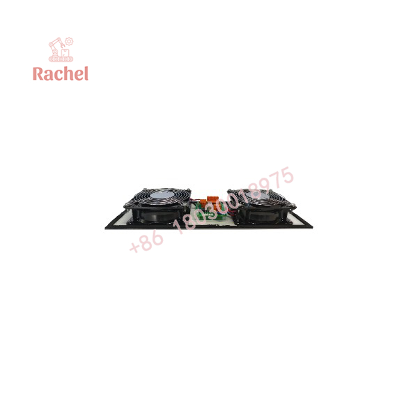
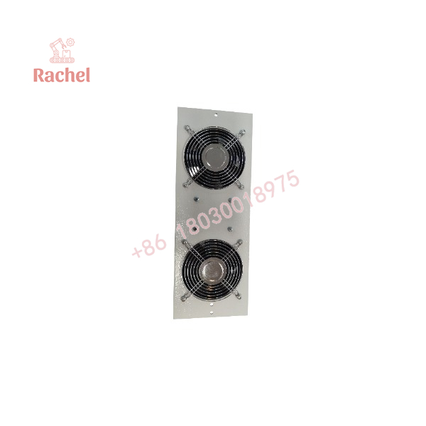
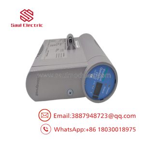
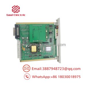
The Honeywell FC-FANWR-24R is a 24 V DC fan assembly associated with the Honeywell Safety Manager system. The assembly comprises two fans and a printed circuit board (PCB 07209) mounted on a plate. Its primary function is to provide cabinet ventilation while generating feedback signals that indicate whether the fans are operating above their minimum speed threshold.
A four-pole connector carries the external DC power and readback wiring. Each fan has a green status LED that illuminates when its speed exceeds the specified minimum. When both fans meet that threshold, the readback contact closes. This arrangement gives the cabinet monitoring system a defined indication of fan operation, supporting maintenance decisions when ventilation performance needs attention.
Key Technical Specifications
| Parameter | Specification |
|---|---|
| Brand | Honeywell |
| Order model | FC-FANWR-24R |
| Related hardware-reference designation | FANWR-24R / FS-FANWR-24R |
| Product type | Dual-fan assembly with status readback |
| System context | Honeywell Safety Manager cabinet |
| Fan quantity | 2 |
| Circuit board | PCB 07209 |
| Supply voltage | 24 V DC |
| Power consumption | 9.5 W |
| Operating voltage range | 12–29 V DC |
| Reverse-polarity protection | Not provided |
| Nominal fan speed | 3,200 RPM |
| Minimum fan speed | 1,500 ± 100 RPM |
| Airflow | 360 m³/h (211.8 CFM) for the complete assembly |
| Noise level | 52 dB |
| Fan status indication | Individual green LED indicators |
| Readback connection | Four-pole connector |
| Maximum readback switched voltage | 300 V DC / 240 V AC |
| Maximum readback switched current | 0.5 A |
| Maximum readback switched power | 10 W |
| Operating temperature range | −30°C to +75°C |
| Ingress protection | IP20 |
| Dimensions (L × W × D) | 391 × 142 × 51 mm |
| Weight | 1.7 kg |
Engineering Selection Highlights
- Dual-fan construction: Two fans share a mounting plate, providing a single assembly for cabinet ventilation rather than two separately mounted fan units.
- Individual fan indication: Each fan has its own green LED, allowing maintenance personnel to identify which fan is below the required speed threshold.
- Readback contact: The contact closes when both fans exceed the minimum-speed threshold, providing a discrete status indication for the monitoring circuit.
- 24 V DC power: The specified supply is 24 V DC, with a documented operating range of 12–29 V DC. The absence of reverse-polarity protection makes correct wiring essential.
- Defined airflow direction: The assembly documentation identifies airflow from inside the enclosure toward the outside. Installation orientation should preserve this direction.
- Four-pole electrical connection: Power and status wiring terminate at the assembly’s four-pole connector, which must match the intended cabinet wiring arrangement.
- Mechanical fit: The 391 × 142 × 51 mm mounting envelope should be checked against the cabinet’s available installation space before replacement.
System Compatibility & Integration Requirements
| Item | Requirement | Practical Note |
|---|---|---|
| Automation system | Honeywell Safety Manager | Confirm that the installed cabinet uses the corresponding fan assembly configuration. |
| Power supply | 24 V DC nominal; 12–29 V DC operating range | Verify polarity and supply suitability before energizing the assembly. |
| Electrical connection | Four-pole connector for power and readback wiring | Check connector orientation and the cabinet wiring assignment. |
| Fan monitoring | Individual LED indication and shared readback contact | The readback contact closes only when both fans exceed the minimum-speed threshold. |
| Mounting | Fan pair and PCB mounted on a common plate | Check the available mounting area and mechanical arrangement. |
| Airflow | Inside-to-outside enclosure airflow | Preserve the specified airflow direction during installation. |
The hardware-reference designation FS-FANWR-24R is also used for this fan unit. When ordering a replacement under the FC-FANWR-24R designation, compare the complete part number and assembly details with the installed unit rather than relying on the shared FANWR-24R suffix alone.
FC-FANWR-24R
FC-FANWR-24R
Dimensions, Mounting & Connection Notes
The FC-FANWR-24R is a plate-mounted assembly containing two fans, a monitoring PCB, and protective finger guards on both sides of the fans.
- Dimensions: 391 × 142 × 51 mm (length × width × depth).
- Weight: 1.7 kg.
- Electrical connector: Four-pole connector for external power and readback wiring.
- Airflow orientation: From inside the enclosure to the outside.
- Fan protection: Finger guards on both sides of the fan assembly.
- Supply polarity: Reverse-polarity protection is not provided.
Before installation, isolate the relevant power supply and follow the cabinet’s approved maintenance procedure. Confirm the connector wiring, polarity, airflow orientation, and mechanical fit before energizing the assembly.
Detailed Product Overview
Dual-fan assembly and ventilation function
The Honeywell FC-FANWR-24R is designed around two fans installed on a common mounting plate with PCB 07209. This integrated arrangement combines ventilation hardware and its associated monitoring electronics in one assembly.
The documented airflow direction is from the inside of the cabinet toward the outside. This orientation is important when installing the unit because reversing the intended airflow can change the enclosure’s ventilation pattern. The fan assembly should be positioned according to the cabinet’s designated mounting arrangement.
Fan-speed indication and readback logic
The assembly includes electronics that generate signals representing fan operating status. Each fan has a green LED that illuminates when its speed exceeds the minimum threshold. The shared readback contact closes when both fans operate above that threshold.
This logic gives maintenance personnel two complementary forms of information. The individual LEDs help identify the fan whose speed has fallen below the threshold, while the readback contact provides a discrete status signal for the cabinet monitoring circuit.
The readback function should not be interpreted as proof that the entire cabinet cooling system is performing adequately. A fan may exceed its minimum speed while airflow is restricted by blocked openings, accumulated dust, or other enclosure conditions.
Electrical supply and connection
The unit operates from a nominal 24 V DC supply and has a documented operating range of 12–29 V DC. Its power consumption is 9.5 W. Because reverse-polarity protection is not provided, supply polarity must be confirmed before power is applied.
External power and readback wiring terminate at a four-pole connector. During replacement, retain the correct wiring assignment for the cabinet and ensure that the readback circuit remains within the specified switched-voltage, current, and power limits.
Environmental and mechanical considerations
The documented operating temperature range is −30°C to +75°C, and the assembly has an IP20 ingress-protection rating. IP20 does not provide protection against water ingress, so the unit must be installed in an enclosure appropriate for the surrounding environment.
The assembly measures 391 × 142 × 51 mm and weighs 1.7 kg. These dimensions should be used to check mounting clearance and mechanical fit. Installation should also preserve the intended airflow path and avoid obstructions that could restrict ventilation.
Replacement identification
When sourcing the FC-FANWR-24R, compare the part number on the installed unit, the fan assembly arrangement, the four-pole connector, and the mounting dimensions. The related FS-FANWR-24R designation appears in Safety Manager hardware documentation, so confirming the full designation helps reduce the risk of ordering a differently configured component.
Applications & System Role
The FC-FANWR-24R serves the cabinet ventilation function within a Honeywell Safety Manager installation. It combines forced-air cooling with a discrete indication of fan operating status.
Its principal engineering roles include:
- Cabinet heat removal: Moves air from inside the enclosure to the outside, helping remove heat generated by installed equipment.
- Fan-condition indication: Provides separate visual status indications for the two fans.
- Remote status monitoring: Supplies a readback contact that changes state when both fans exceed the specified minimum speed.
- Maintenance support: Helps personnel distinguish a fan-speed problem from other cabinet issues during inspection and troubleshooting.
- Ventilation-system replacement: Provides a defined assembly configuration for maintenance work where the installed hardware and electrical connections match.
The readback contact is a fan-status indication, not a direct measurement of cabinet temperature or airflow volume. Cabinet thermal performance still depends on the installed equipment’s heat load, enclosure design, airflow restrictions, and ventilation arrangement.
FAQ
What is the Honeywell FC-FANWR-24R?
The Honeywell FC-FANWR-24R is a 24 V DC dual-fan assembly with electronic fan-status monitoring, intended for the Honeywell Safety Manager cabinet ventilation arrangement.
What voltage does the FC-FANWR-24R require?
It uses a nominal 24 V DC supply and has a documented operating range of 12–29 V DC. The assembly does not provide reverse-polarity protection.
How does the fan readback function work?
Each fan has a green LED that illuminates when its speed exceeds the minimum threshold. The shared readback contact closes when both fans exceed that threshold.
What is the airflow capacity of the FC-FANWR-24R?
The documented airflow for the complete assembly is 360 m³/h, equivalent to approximately 211.8 CFM.
What are the dimensions of the FC-FANWR-24R?
The assembly measures 391 × 142 × 51 mm and weighs 1.7 kg.
What is the operating temperature range?
The documented operating temperature range is −30°C to +75°C. The assembly has an IP20 ingress-protection rating.
What should be checked before replacing the fan assembly?
Check the complete part designation, supply voltage and polarity, four-pole connector wiring, mounting dimensions, and required airflow direction. After installation, check the individual fan indicators and confirm that the readback contact operates according to the specified logic.

 Start Chat


