





Description
Product Introduction & Engineering Value
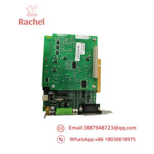
The KUKA DSE-IBSC33-1 is a component of the KRC2 controller’s servo-electronics architecture, rather than a conventional standalone PLC I/O card. It is installed on the MFC3 and provides the interface between the controller and KUKA servo modules.
This makes accurate identification important. A replacement must match the KRC2 controller generation, MFC3 configuration, DSE version, and robot-axis architecture. If the robot has more than eight axes, KUKA documentation calls for additional DSE-IBS-C33-AUX hardware.
Technical Specifications
| Parameter | Specification |
|---|---|
| Manufacturer | KUKA |
| Model | DSE-IBSC33-1 |
| Related Designation | DSE-IBS-C33 |
| Module Type | Digital servo electronics |
| Controller | KUKA KRC2 |
| Carrier Board | MFC3 |
| Primary Function | Servo-module interface and control |
| Status Processing | Processes servo-module error and operating information |
| Servo System | KUKA DSE / KSD architecture |
| Maximum DSE Modules on MFC3 Standard | 2 |
| Extended-Axis Requirement | DSE-IBS-C33-AUX for systems exceeding 8 axes |
| Typical Application | KUKA industrial robot controller |
KUKA’s KRC2 documentation states that an MFC3 Standard card can accommodate a maximum of two DSE-IBSC33 modules.
For robots using more than eight axes, KUKA specifies an additional DSE-IBS-C33-AUX board. This is particularly relevant to systems with external axes or expanded servo configurations.
What the DSE actually does
The DSE sits between the KRC2 controller electronics and the servo system. KUKA describes it as controlling the servo modules while processing the error and operating-condition information received from those modules.
That distinction is important during troubleshooting. A DSE-related fault does not necessarily mean that the KSD drive or motor has failed.
Field Application & the “Trench” Experience
A typical KRC2 maintenance job starts with a robot that powers up but refuses to enter normal servo operation. The KCP reports a servo-related fault, yet the individual KSD modules appear physically normal.
An experienced technician does not immediately replace the drive. The controller cabinet is checked first: MFC3 status, DSE connections, DSE module seating, servo-bus connections, KSD status, and the controller’s diagnostic messages are reviewed together.
The DSE-IBSC33-1 is particularly relevant in this situation because it is the interface responsible for communicating with the servo modules and processing their status information.
Niche application scenarios
- Six-axis KUKA welding robot: Maintaining the servo communication path between the KRC2 controller and the six robot-axis drives.
- KRC2 handling cell with external positioner: Supporting the controller’s servo architecture when additional external axes are integrated.
- Legacy automotive assembly robot: Keeping an existing KRC2 cabinet operational when the original DSE hardware is no longer readily available from normal production channels.
- Robot refurbishment program: Maintaining tested DSE spares alongside KSD drives, RDC hardware, MFC3 boards, and KCP equipment.
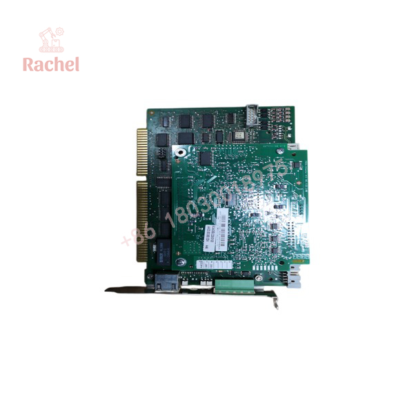
DSE-IBSC33-1
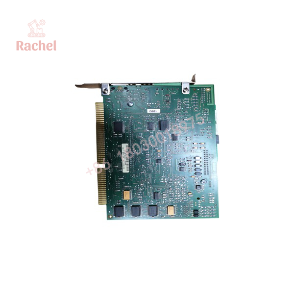
DSE-IBSC33-1
Transparency SOP: QA & Testing
For New Surplus inventory, the verification process should include:
- Part-number verification — Confirm the exact DSE-IBSC33 designation and any suffix such as
-1.40. - Board inspection — Check the PCB, components, connectors, mounting hardware, and edge contacts for storage or handling damage.
- MFC3 compatibility check — Verify that the customer’s controller uses the appropriate MFC3 architecture.
- Power-up verification — Where a compatible KRC2 test environment is available, confirm normal controller initialization.
- Servo communication test — Test communication with compatible KUKA servo hardware rather than relying solely on a visual inspection.
- Diagnostic verification — Check that the controller recognizes the DSE and correctly reports connected servo-module information.
For refurbished inventory, the supplier should clearly distinguish between visual inspection, power-up testing, and full KRC2 servo-system functional testing.
Those are three different levels of verification.
The Veteran’s Tech Trap Guide
⚠️ Trap #1 — Don’t confuse DSE with KSD.
The DSE-IBSC33 is the servo-electronics interface/control module. KSD modules are the servo drives. A KSD fault and a DSE communication fault can produce related symptoms, but they are not the same hardware failure.
⚠️ Trap #2 — Check the MFC3 configuration.
The DSE-IBSC33 is plugged into the MFC3. KUKA specifies a maximum of two DSE-IBSC33 modules on an MFC3 Standard card.
⚠️ Trap #3 — External axes change the equation.
If the robot configuration exceeds eight axes, KUKA specifies additional DSE-IBS-C33-AUX hardware. Do not diagnose an expanded-axis system using the same assumptions as a standard six-axis robot.
PRO TIP: Before removing the original DSE, photograph the module’s complete label and its installation position on the MFC3. Also record the KRC2 cabinet generation and the number of configured axes. That information can prevent an otherwise avoidable compatibility problem.
Dynamic FAQ
What is the KUKA -1?
It is a digital servo-electronics module for KUKA KRC2 controllers. It plugs into the MFC3 and controls/interconnects the KUKA servo modules while processing servo status and fault information.
Is -1 the same as DSE-IBS-C33?
The KUKA documentation uses the designation DSE-IBS-C33, while secondary inventory listings use forms such as -1.40. Because suffixes can identify specific hardware versions, compare the complete installed part number before treating two units as interchangeable.
Which KUKA controller uses this module?
The DSE-IBS-C33 is documented as part of the KRC2 controller’s MFC3 servo architecture.
How many DSE modules can an MFC3 Standard card accommodate?
KUKA documentation states that the MFC3 Standard can accommodate up to two DSE-IBSC33 modules.
What happens when a KRC2 robot has more than eight axes?
KUKA specifies an additional DSE-IBS-C33-AUX board for configurations exceeding eight axes. This is relevant to systems incorporating multiple external axes.
How should New Surplus authenticity be verified?
Confirm the complete KUKA part designation, inspect the PCB and connectors, and request photographs of the actual unit. For a production robot, the preferred spare should have documented functional testing in a compatible KRC2/DSE environment. Also confirm the warranty period, DOA policy, and return conditions in writing.

 Start Chat


