





Description
Product Introduction
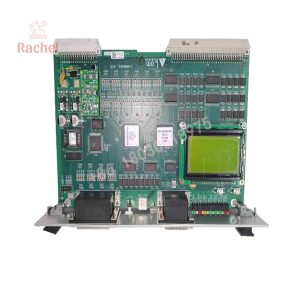
The Lam Research 810-800081-022 is a critical circuit board assembly designed for central communication and signal conditioning across 200mm and 300mm Lam semiconductor processing platforms. Operating within the main tool rack of 2300, Kiyo, and Exelan systems, this card routes real-time commands between the host CPU, chamber I/O racks, and localized subsystem controllers.
Built to withstand the electrical demands of semiconductor manufacturing, the 810-800081-022 features isolated signal drivers that prevent noise coupling from high-frequency RF match networks. By maintaining precise logic timing and steady communication handshakes, this module ensures smooth recipe execution and prevents false tool interlocks during critical etch and deposition cycles.
Key Technical Specifications
| Parameter | Value |
| Manufacturer | Lam Research |
| Board Part Number | 810-800081-022 |
| Assembly Part Number | 855-800081-022 |
| Board Function | System Controller Interface / Signal Router PCB |
| Tool Compatibility | Lam 2300, Kiyo, Vector, Exelan Series |
| Operating Voltage | 24V DC (Backplane / Aux Powered) |
| Signal Processing | Mixed High-Speed Digital Logic & Analog Buffering |
| Form Factor | Multi-Layer PCB / Plug-in Card Cage Module |
| Operating Temperature | 0°C to +55°C (Chassis Internal) |
Application Scenarios & The “Trench” Experience
Picture this: It is 2 AM on a Sunday, and your highest-yield 300mm etch chamber drops off the network with a permanent “Host Controller Communication Timeout.” Re-booting the tool fails to clear the fault, leaving a batch of critical-path wafers stranded in the load lock. The root cause isn’t a corrupt software file—it’s a failed transceiver array on the system controller PCB inside the bay cabinet. In a fast-paced wafer fab, every hour of unscheduled tool downtime burns tens of thousands of dollars in lost throughput.
- Conductor & Dielectric Etch Platforms (2300 / Kiyo) – Coordinates high-speed telemetry between the host computer, chamber gas boxes, and vacuum management systems.
- Thin Film Deposition Tools (Vector Series) – Manages localized multi-channel digital interlocks for chamber isolation valves and RF generator enables.
- Subsystem Rack Routing – Isolates logic signals from ambient electromagnetic noise generated by nearby high-power RF match networks.
Field Replacement Case: A fab in Arizona experienced intermittent recipe aborts due to communication frame drops on a 2300 chamber. Diagnostics showed thermal degradation on an old controller card’s logic bus buffers. Swapping the faulty board with a fully bench-tested 810-800081-022 unit restored clean signal timing, bringing the chamber back into production qualification in under 40 minutes.
Transparency SOP: Quality Assurance & Testing
We don’t just ship boxes; we test them on actual bench rigs before signed clearance:
- Inbound Visual Inspection: Check under magnification for trace micro-cracks, component heat stress, pin oxidation, and original solder mask integrity.
- Power-Rail & Thermal Scan: Apply 24V DC bench power to measure baseline current draw and monitor thermal profiles using FLIR imaging to catch degraded passives.
- Logic & Bus Communication Test: Seat the card in a test rack to verify address decoding, bus handshakes, and logic state transitions under full signal load.
- Signal Line Integrity: Check digital switching performance and differential signal waveforms on a high-bandwidth oscilloscope to ensure clean noise margins.
- Anti-Static Packaging: Flush multi-pin edge connectors with electrical contact cleaner, seal the module in a static-shielding ESD bag, and pack in custom high-density foam shipping boxes.
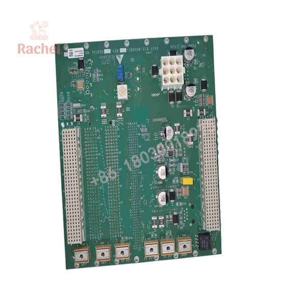
810-800081-022
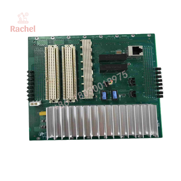
810-800081-022
The Veteran’s Tech Trap Guide (Crucial Value-Add)
- ⚠️ Match Suffix Revision Numbers: Always double-check the dash number (e.g.,
-022vs.-018or-024). Lam occasionally updates onboard PAL/GAL logic or timing capacitors between revisions. Installing an incompatible dash number can cause communication timing faults on boot. - ❗ Never Pull Under Power: Pulling an 810-800081-022 card while the system 24V DC bus is live can cause voltage arcs across dense connector pins. Always kill power to the card cage enclosure before extraction.
- ⚠️ Align Card Guides Carefully: Backplane multi-pin connectors are easily damaged if inserted crookedly. Guide the board smoothly down the card rails and seat it firmly using balanced, straight pressure on both ejector handles.
- ❗ Verify Chassis Grounding: Corroded ground straps or loose card cage mounting screws allow stray RF noise from plasma match units to bleed into logic lines, causing random communication drops that mimic a dead board.
Frequently Asked Questions (FAQ for Conversion)
Q: Is the 810-800081-022 board hot-swappable?
A: No. Extracting this card live can damage edge connectors and trigger DC bus transients across adjacent cards in the rack. Shut down power to the cabinet before servicing.
Q: What is the difference between part number 810-800081-022 and 855-800081-022?
A: The 810- prefix denotes the bare PCB or board-level part number, while the 855- prefix represents the fully populated top-level printed circuit board assembly (PBA) ready for tool installation.
Q: Does this card require firmware flashing upon installation?
A: Typically no. The board functions as a hardware-level interface card. The main tool host controller automatically initializes communication with the card during system boot.
Q: Why buy Surplus or Refurbished stock over ordering directly from the OEM?
A: OEM lead times for legacy 200mm/300mm tool electronics can stretch for weeks or months. Our pre-tested surplus stock ships immediately, allowing you to restore tool operation without long lead times.
Q: What warranty comes with this module?
A: We back all our 810-800081-022 boards with a full 12-month replacement warranty. If the card fails under normal operating conditions within 365 days, we will replace it or issue a full refund.

 Start Chat


