





Description
Product Introduction
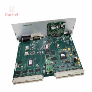
The Lam Research 810-801237-021 is a high-precision stepper driver interface printed circuit board designed for precision motion control within Lam 200mm and 300mm semiconductor manufacturing platforms. Installed in the electronics rack of 2300, Kiyo, and Vector tool sets, this module coordinates real-time step and direction pulses between the main system controller and drive amplifiers managing chamber motion mechanisms.
In automated wafer processing, mechanical subsystems such as pin lifts, throttle valves, slit valves, and variable match capacitors demand exact positioning. The 810-801237-021 integrates dedicated opto-isolation barriers and high-speed differential line drivers, shielding micro-stepping logic from severe electromagnetic interference (EMI) generated by surrounding high-power RF plasma generators.
Key Technical Specifications
| Parameter | Value |
| Manufacturer | Lam Research |
| Board Part Number | 810-801237-021 |
| Assembly Part Number | 855-801237-021 |
| Board Function | Stepper Driver Interface / Motion Control PCB |
| Tool Compatibility | Lam 2300, Kiyo, Vector, Alliance Series |
| Operating Voltage | 24V DC Logic / 48V DC Motor Power Loop |
| Signal Processing | Opto-Isolated Step/Dir Generation & Quadrature Encoder Feedback |
| Form Factor | Multi-Layer PCB / Slot-Mounted Rack Card |
| Operating Temperature | 0°C to +55°C (Chassis Internal) |
Application Scenarios & The “Trench” Experience
Picture this: You are running an advanced-node production wafer lot at 1 AM when Chamber 2 halts abruptly with a “Wafer Lift Pin Position Error.” A cassette of silicon sits trapped mid-transfer inside the transfer module, threatening process yield and halting the entire bay. Replacing the physical stepper motor yields nothing; the actual culprit is a blown line transceiver IC on the stepper driver interface card. When motor pulses drop out on this board, the system loses axis sync and aborts the recipe immediately to prevent robot-wafer collisions.
- Chamber Wafer Lift Mechanics – Manages precise vertical motion and velocity profiling for wafer lift pins during transfer sequences.
- Exhaust Throttle Valves (Vat / Nor-Cal Valves) – Controls fine angular step execution on exhaust pressure valves to maintain precise chamber millitorr setpoints.
- RF Match Capacitor Drives – Adjusts physical motor-driven tuning capacitors under load to optimize RF power delivery into plasma fields.
Field Replacement Case: A 300mm fab in Singapore suffered recurring “Throttle Valve Motion Stalls” on a Kiyo etch chamber. Oscilloscope diagnostics revealed signal attenuation on an aging 810-801237 card’s differential step output. Swapping in a bench-tested 810-801237-021 board restored razor-sharp pulse transitions instantly, getting the tool back through qualification in under 50 minutes.
Transparency SOP: Quality Assurance & Testing
We don’t just ship boxes; we test them on actual bench setups before signing off for shipment:
- Inbound Microscopic Inspection: Check PCB traces, solder masks, and card edge connectors under high magnification for micro-fractures, burn marks, or pin oxidation.
- Power Rail Integrity Test: Apply 24V DC logic power to verify quiescent current draw and detect leaky capacitors using FLIR thermal imaging.
- Motion Pulse Waveform Verification: Drive high-frequency step/direction pulses into dummy loads while checking differential outputs on an oscilloscope for clean rise/fall times.
- Encoder Feedback Handshake: Inject simulated quadrature encoder signals to confirm zero frame loss or counting drift across all feedback channels.
- Anti-Static Packaging: Clean connector fingers with electrical contact spray, seal the board in a conductive ESD shield bag, and ship in custom foam-lined boxes.
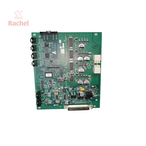
810-801237-021
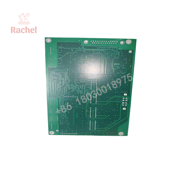
810-801237-021
The Veteran’s Tech Trap Guide (Crucial Value-Add)
- ⚠️ Match Suffix Revisions Carefully: Always verify the dash suffix (e.g.,
-021vs.-001or-005). Lam modifies onboard PAL logic, encoder divider ratios, and step timing intervals between dash revisions. Installing an mismatched suffix can cause axis calibration errors or over-travel faults upon homing. - ❗ Never Pull Under Power: Pulling an 810-801237-021 board while the 24V/48V DC bus is live can trigger inductive arc spikes across backplane connector pins, frying delicate onboard optocouplers. Always kill rack power before extraction.
- ⚠️ Verify Limit Switch Interlocks: After replacing this card, manually cycle the associated motor homing sequence while watching limit switch indicators. A sticking home or end-of-travel sensor will simulate a faulty driver board and cause drive timeouts.
- ❗ Inspect Card Rail Alignment: Multi-pin backplane connectors are easily damaged if inserted crookedly. Align the board along the card cage guide rails and apply even, straight pressure on the card ejector handles.
Frequently Asked Questions (FAQ for Conversion)
Q: Is the 810-801237-021 board hot-swappable?
A: No. Extracting this card live risks damaging edge connectors and triggering DC bus voltage transients across adjacent cards. Power down the module enclosure before replacement.
Q: What is the difference between part number 810-801237-021 and 855-801237-021?
A: The 810- prefix denotes the bare PCB or unpopulated sub-assembly, while the 855- prefix indicates the complete, fully populated top-level printed circuit board assembly (PBA) ready for tool installation.
Q: Does this stepper interface board require software flashing upon installation?
A: Typically no. The board functions primarily as a hardware signal conditioning and driver logic interface. Once installed, the host motion controller automatically handles axis initialization during tool boot-up.
Q: Why buy Surplus or Refurbished stock over ordering directly from the OEM?
A: Lead times for legacy 200mm and 300mm motion control parts from the OEM can stretch for weeks or months. Our pre-tested surplus stock ships immediately, allowing you to restore tool operation without waiting on factory production lead times.
Q: What warranty comes with this module?
A: We back all our 810-801237-021 units with a full 12-month replacement warranty. If the card fails under normal operating conditions within 365 days of purchase, we will replace it or issue a full refund.

 Start Chat


