





Description
Core Product Summary (Brand / Model / Key Attributes)
The Mitsubishi FX2N-128MR-001 is the largest capacity main base processing unit in the MELSEC-F FX2N series of compact programmable logic controllers. Featuring 128 integrated digital I/O points—configured as 64 24V DC inputs and 64 relay outputs—it serves as a high-density, centralized control solution for medium-to-large machinery, packaging equipment, automated assembly cells, and material handling systems.
Powered by a wide-range 100–240 V AC supply voltage, the base controller executes basic program instructions at 0.08 µs per instruction. It incorporates an 8,000-step RAM memory (expandable up to 16,000 steps via memory cassette), a built-in real-time clock, and support for up to eight right-side expansion or special function modules to scale total system capacity up to 256 local I/O or 384 remote CC-Link I/O points.
Key Technical Specifications
| Parameter | Specification |
| Product Type | Programmable Logic Controller (PLC) Main Base Processing Unit |
| Series / Family | MELSEC-F Series (FX2N Generation) |
| Power Supply Voltage | 100–240 V AC (+10%, -15%), 50/60 Hz |
| Power Consumption | 100 VA |
| Integrated Digital Inputs | 64 points (24 V DC, sink/source configurable) |
| Integrated Digital Outputs | 64 points (Electromechanical Relay) |
| Relay Output Rating | Max. 2 A per output (250 V AC / 30 V DC); 8 A per group |
| Processing Speed | 0.08 µs per basic instruction |
| Program Memory | 8,000 steps built-in RAM (expandable to 16,000 steps) |
| High-Speed Counters | 1-phase (up to 60 kHz, 2 points) / 2-phase (up to 30 kHz, 1 point) |
| Dimensions (W × H × D) | 350 mm × 90 mm × 87 mm |
| Weight | 1.8 kg |
Detailed Product Overview
The Mitsubishi FX2N-128MR-001 provides the highest density of onboard I/O within the FX2N product family. Functioning as both a standalone controller and the central hub of an expanded system, it coordinates digital logic, high-speed counting, and multi-axis positioning without requiring additional racks or local backplane sub-racks.
Its internal processing architecture delivers execution speeds six times faster than earlier FX generation processors, optimizing cycle times for high-speed automated processes. The 64 DC input terminals feature photocoupler isolation between field lines and controller logic, smoothing noise and transients. The 64 electromechanical relay outputs handle switching voltages up to 250 V AC or 30 V DC, allowing direct control of contactors, solenoid valves, indicator lights, and low-power actuators.
System expansion is facilitated through a right-hand extension bus connector. Users can snap on additional input/output expansion blocks, analog I/O modules, temperature control units (such as the FX2N-2LC), pulse train/positioning units, or serial communication interfaces (RS-232, RS-422, RS-485).
Engineering Selection Highlights
- High Onboard I/O Capacity: Combines 64 digital inputs and 64 relay outputs inside a single 350 mm wide enclosure, reducing required cabinet space compared to modular rack systems.
- 0.08 µs Instruction Speed: High-speed execution ensures consistent scan times even when handling complex math operations and multi-tier logic blocks.
- Flexible Memory Options: Ships with an 8,000-step RAM memory that can be upgraded to 16,000 steps via optional EEPROM/EPROM cassettes (FX-RAM-8 / FX-EPROM-8).
- Onboard High-Speed Inputs: Integrates dedicated high-speed counter inputs up to 60 kHz, supporting direct quadrature encoder feedback and pulse counting.
- Universal AC Input Power: Operates reliably across international plant power standards ranging from 100 V AC to 240 V AC.
- Modular Bus Architecture: Connects up to eight special function modules directly to the right side of the main unit without requiring external backplane hardware.
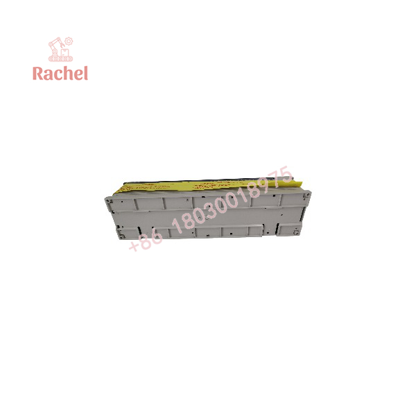
FX2N-128MR-001
System Compatibility & Integration Requirements
| Item / Dependency | Verified Compatibility or Requirement | Practical Note |
| Programming Software | GX Developer, GX Works2 (FX CPU mode), FX-20P-E handheld programmer | Connects via front RS-422 programming port. |
| Expansion Modules | FX2N Series I/O extension blocks and special function blocks | Attaches directly via the right-side bus connector. |
| Memory Expansion | FX-RAM-8, FX-EPROM-8 Memory Cassettes | Inserts into the front memory slot to increase program capacity up to 16,000 steps. |
| Communications Option | FX2N-232-BD, FX2N-422-BD, FX2N-485-BD boards | Mounts into the left-side communication board expansion slot. |
| Network Connectivity | CC-Link via FX2N-16CCL-M module | Expands system capacity up to 384 CC-Link remote points. |
Dimensions, Mounting & Connection Notes
The Mitsubishi -128MR-001 measures 350 mm in width, 90 mm in height, and 87 mm in depth, with a net weight of approximately 1.8 kg.
Installation is supported either by direct surface mounting using M4 screws or by clipping onto a standard 35 mm DIN rail (TS35). Field wiring connects through screw terminal blocks positioned across the top and bottom edges of the module housing. Terminal screws accept wire sizes up to 2.5 mm² (AWG 14). Maintain at least 50 mm of vertical clearance above and below the base unit inside the electrical panel to facilitate proper convective cooling and cable routing.
FAQ
What is the Mitsubishi FX2N-128MR-001?
It is a compact main processing base unit PLC from Mitsubishi Electric’s MELSEC-F FX2N series, featuring 64 digital inputs and 64 relay outputs.
What is the maximum I/O point capacity of this base unit?
The unit includes 128 integrated I/O points on board and can be expanded up to 256 local I/O points (or 384 remote points via CC-Link).
What power supply voltage does the FX2N-128MR-001 require?
It operates on an AC power supply range of 100 V AC to 240 V AC at 50/60 Hz.
What is the output relay specification?
The electromechanical relay outputs support a maximum switching voltage of 250 V AC or 30 V DC, with a maximum current rating of 2 A per channel (8 A per common group).
How fast is the CPU instruction processing time?
The CPU processes basic sequence instructions at a speed of 0.08 µs per instruction.
What software is used to program the FX2N-128MR-001?
Programming is performed using Mitsubishi software such as GX Developer or GX Works2 using ladder logic / step ladder formats.
Verification & Troubleshooting Notes
- POWER LED Diagnostic: If the POWER LED on the front panel is unlit, verify that line voltage between 100 V AC and 240 V AC is present across the L and N terminals and check the internal power supply fuse.
- PROG.E / ERROR LED Faults: A flashing ERROR LED indicates a program logic, syntax, or memory cassette error; a solid red ERROR LED indicates CPU execution fault. Connect programming software to read the PLC error code.
- BATT.V (Battery) Alarm: A lit BATT.V indicator signifies that the internal memory backup battery voltage has dropped below operational limits. Replace the backup battery unit while keeping the controller powered or within memory hold limits.
- Output Channel Isolation: If a specific output channel fails to switch a load, check the channel fuse/relay contact status and confirm that external switching voltage does not exceed the 2 A / channel maximum limit.

 Start Chat


