





Description
Product Introduction & Engineering Value
When two machine shafts must remain synchronized under changing speed or load, a basic speed reference is not enough. The BY150 continuously compares encoder feedback from the master and slave sides and generates an analog correction signal to maintain the required relationship. It can work with AC, DC, and servo drives that accept a 0–10 V speed reference.
The unit is particularly useful on legacy machinery where replacing the complete drive-control architecture would create unnecessary commissioning work. Its digital ratio, phase, index, and registration functions allow the original machine-control concept to remain intact.
Technical Specifications
| Parameter | Specification |
|---|---|
| Manufacturer | Motrona |
| Model | BY150 |
| Function | High-performance drive synchronizer |
| Application | Two-drive synchronization and registration |
| Encoder Counting Frequency | Up to 300 kHz |
| Encoder Type | Incremental quadrature |
| Counting Modes | x1, x2, x4 |
| Encoder Signals | A, /A, B, /B, Z, /Z, 5 V TTL |
| Dynamic Response | Approximately 100 µs |
| Analog Speed Interface | 0–10 V |
| Analog I/O Range | ±10 V for applicable analog connections |
| Power Supply | 24 VDC nominal |
| Permitted Supply Range | 18–30 VDC |
| Serial Communication | RS232 / RS485 |
| Network Option | CANopen |
| Memory | EEPROM and RAM |
| Mounting | 19-inch aluminum cassette; DIN rail possible with SM150 backplane |
| Control Functions | Ratio, phase, index, print-mark registration, trim, reversal |
The manufacturer documentation states that the 300 kHz figure refers to the total number of counted encoder edges. Consequently, maximum encoder frequency changes with the selected x1/x2/x4 counting mode.
Field Application & the “Trench” Experience
A converting line running two mechanically linked rollers began showing gradual registration drift after acceleration. Both drives were operating normally when checked individually. The problem appeared only when the machine entered production speed.
The maintenance engineer traced the issue to synchronization rather than drive failure. The BY150 compares master and slave encoder positions and applies an analog correction to the slave speed reference. After the encoder wiring and scaling parameters were verified, the synchronization loop could once again compensate for the small speed differences between the two drives.
This architecture is particularly relevant to:
- Printing registration systems where print marks must remain aligned with a moving web.
- Flying shear and rotary cutter applications requiring phase tracking between a material feed and cutting axis.
- Packaging lines where two independent drives must maintain a defined ratio.
- Feed-roll and tension systems where the slave speed is continuously corrected against a master encoder.
- High-speed conveying and winding equipment requiring positional rather than merely approximate speed synchronization.
The BY150 documentation specifically identifies flying shears, rotating cutters, positioning systems, and print-mark registration as applicable uses.
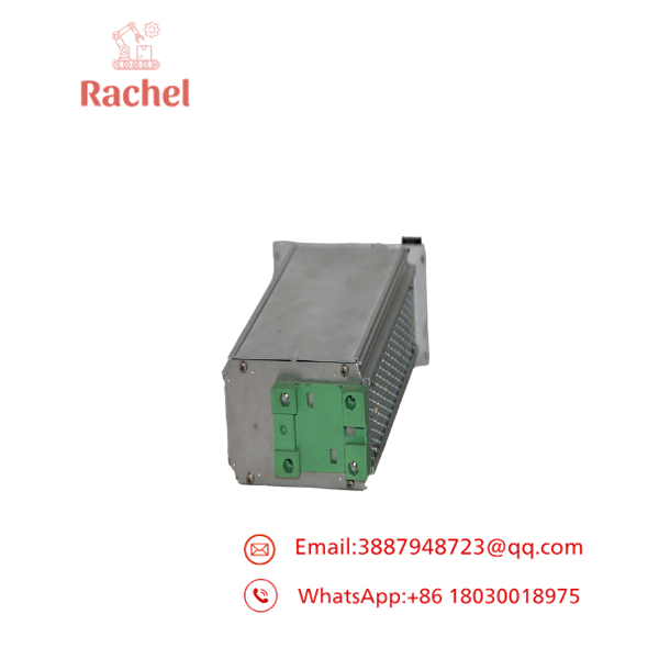
BY150
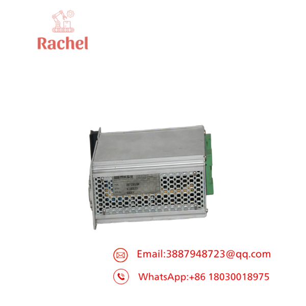
BY150
Transparency SOP: QA & Testing
For New Surplus or Refurbished BY150 inventory, testing should go beyond a simple power-up.
1. Identification check
Verify the BY150 model, front-panel labeling, connectors, hardware revision, and physical configuration.
2. Power test
Apply a controlled 24 VDC supply and verify that the unit operates within its specified 18–30 VDC range.
3. Encoder interface test
Use a suitable incremental encoder simulator to verify A/B quadrature counting and, where applicable, index-pulse recognition.
4. Analog I/O test
Check the speed-reference and correction-output circuitry using calibrated test equipment.
5. Communication test
Where required, verify the applicable RS232/RS485 interface and communication functions.
6. Functional synchronization test
The best test uses representative master/slave pulse inputs and a controllable analog output/load arrangement to confirm scaling, ratio correction, phase adjustment, and registration behavior.
The Veteran’s Tech Trap Guide
⚠️ 300 kHz does not mean 300 kHz encoder frequency in every mode.
The BY150 counts encoder edges. At x2 and x4 evaluation, the permissible physical pulse frequency is correspondingly lower. For example, the documentation specifies 300 kHz at x1, 150 kHz at x2, and 75 kHz at x4.
⚠️ Do not ground the analog reference casually.
The installation documentation warns about ground loops between the power supply and speed-reference circuitry. Improper grounding can introduce errors into the analog synchronization signal.
PRO TIP: Verify the master and slave encoder scaling before adjusting the correction gain. If the scaling is wrong, increasing gain may hide the symptom temporarily while making the synchronization loop more difficult to stabilize.
⚠️ The BY150 cannot compensate for an undersized drive.
The controller can correct synchronization errors only within the physical speed and torque capability of the connected drives. The documentation explicitly states that the drives themselves must be correctly dimensioned for the required dynamics.
Dynamic FAQ
Q1. What is the Motrona BY150?
The BY150 is a high-performance synchronizer for two independently controlled drives. It compares encoder feedback and produces correction signals to maintain speed, ratio, phase, or positional synchronization.
Q2. What encoder signals does BY150 support?
The documentation specifies full-quadrature 5 V TTL encoder inputs, including A, /A, B, /B, and index signals Z and /Z. Counting can be configured for x1, x2, or x4 evaluation.
Q3. What is the BY150 power requirement?
It operates from an unstabilized 24 VDC supply, with an allowable range of 18–30 VDC.
Q4. Can BY150 control servo drives?
Yes. The documentation specifically states that it can be used with AC, DC, and servo drives that operate from a 0–10 V speed reference. Its approximately 100 µs response is intended for dynamic synchronization applications.
Q5. Does BY150 support CANopen?
Yes. RS232/RS485 communication is provided, while CANopen is available as an option according to the documentation.
Q6. Is New Surplus BY150 inventory the same as refurbished inventory?
No. New Surplus should mean unused original equipment that has entered secondary inventory channels. Refurbished equipment has previously been installed or otherwise requires restoration/testing. For either condition, request the actual part number, photographs, test scope, and written warranty before purchasing.
Warranty: Coverage depends on the supplier and stock condition. For refurbished BY150 units, confirm that the warranty covers functional failure rather than only arrival condition.


 Start Chat


