





Description
Product Introduction
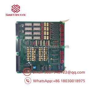
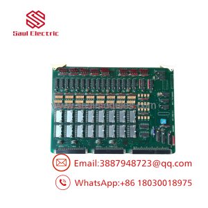
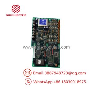
The NABCO MCA-901-11A (Part Number 885-73748388) is a specialized marine-grade main microcomputer logic board manufactured by Nabtesco/NABCO. Built specifically for marine main engine remote control consoles, governor control racks, and vessel maneuvering systems, this card serves as the central processing unit for system telemetry and operational commands.
Featuring an L-shaped board footprint, integrated microprocessors, diagnostic status LEDs, and multiple ribbon cable connectors (CN5–CN11), the MCA-901-11A processes bridge order telegraph signals, governor feedback, and safety interlocking logic. It provides real-time signal arbitration in demanding marine and industrial automation environments.
Key Technical Specifications
| Parameter | Specification |
| Manufacturer | NABCO / Nabtesco Corporation |
| Model Number | MCA-901-11A |
| OEM Part Number | 885-73748388 (also referenced as 885/73748388) |
| Board Category | Main Microcomputer Logic & Processing PCB |
| Primary Application | Marine Main Engine Remote Control & Automation Racks |
| Control Logic | Microprocessor-based Command Processing & Interlock Logic |
| Diagnostics | Onboard LED Status Indicators (COM 1, COM 2, CONN) |
| Interface Connectors | Multi-Pin Ribbon Cable Headers (CN5, CN6, CN7, CN8, CN9, CN11) |
| Form Factor | Multi-Layer L-Shaped Sub-Rack Modular PCB |
| Operating Temp Range | -10°C to +60°C (14°F to 140°F) |
Application Scenarios & The “Trench” Experience
The Trench Story
It is 1:30 AM on a container vessel preparing to drop anchor in a busy harbor channel. A communication drop occurs between the bridge control console and the engine room sub-rack, triggering a persistent “Control CPU Fault” alarm on the maneuvering panel. The engine management system fails to respond to bridge lever adjustments, locking the engine in manual mode. Swapping in a pre-tested surplus MCA-901-11A microcomputer logic board restores communication channels and command processing within 20 minutes, allowing the vessel to safely navigate into port.
Application Scenarios
- Marine Bridge & Engine Room Consoles – Arbitrates telegraph commands, speed settings, and directional interlocks for ship propulsion.
- Main Engine Remote Control Racks – Processes feedback signals from speed governors, shaft tachometers, and position actuators.
- Vessel Safety Interlock Systems – Evaluates trip signals and override conditions to protect main engines from catastrophic overspeed or oil pressure drops.
- Marine Power Management Systems – Coordinates multi-generator load distribution and automated start/stop sequences.
Field Case Study
A marine automation engineer reported a complete loss of communication between the bridge maneuvering stand and the engine governor rack during sea trials. Troubleshooting revealed localized component degradation on the original logic PCB caused by long-term thermal cycle exposure inside the control cabinet. We bench-tested a surplus MCA-901-11A logic board on a simulated marine control rack, verified serial transmission lines and logic processing, and dispatched it via port-side delivery. The engineer mounted the board, reconnected the ribbon harnesses, and verified full system synchronization instantly.
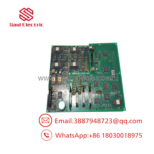
MCA-901-11A
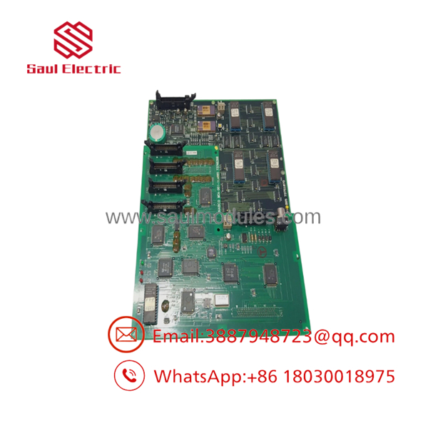
MCA-901-11A
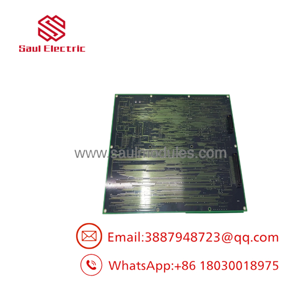
MCA-901-11A
Transparency SOP: Quality Assurance & Testing
- Inbound Visual & Optical Inspection: We check all PCB traces, solder connections, and IC packages under magnification for heat degradation or physical damage, verifying genuine NABCO labels and part stampings (885-73748388).
- Connector & Pin Verification: All ribbon cable headers (CN5–CN11) and terminal pins are cleaned and inspected for oxidation, bending, or contact wear.
- Bench Rig Power & Diagnostic Testing: The card is mounted into a test rack to verify logic boot routines, internal voltage rail integrity, and onboard LED diagnostic indications (COM 1, COM 2, CONN).
- Signal Communication Verification: We send and receive simulated telegraph commands and feedback signals across connector channels to confirm microprocessor responsiveness and logic timing.
- ESD Anti-Static Packaging: Cleared boards undergo non-conductive terminal cleaning before being sealed inside static-shielding bags with foam impact protection.
The Veteran’s Tech Trap Guide
- ⚠️ Confirm Full Part Number Alignment: ❗ Verify both the “MCA-901-11A” model designation and the silk-screened “885-73748388” part number on your original board. Revisions within the 885 series can feature different EEPROM firmware versions or altered pinouts.
- ❗ Never Connect Ribbon Cables Under Power: Always turn off primary DC power to the control cabinet before removing or inserting ribbon cable plugs. Plugging headers into a live board can cause pin misalignment and short sensitive microprocessor lines.
- ⚠️ Handle EEPROM & Socketed ICs with Care: If swapping socketed IC chips or firmware PROMs from an old board to a replacement board, use an IC extractor tool and adhere to strict ESD grounding protocols to prevent static discharge damage.
- ❗ Verify Auxiliary Power Rail Stability: Before installing the new logic PCB, check that upstream power supply cards (such as the MCA-601-01) are delivering stable, ripple-free DC voltages to the rack backplane.
Frequently Asked Questions (FAQ for Conversion)
Q: What do the onboard COM 1, COM 2, and CONN LEDs indicate on the board?
A: These LEDs provide real-time diagnostic status for serial communication channels and system connection links between the logic board and external maneuvering stands or governor racks.
Q: Is the NABCO board hot-swappable?
A: No. System power must be completely isolated before removing or installing this board. Pulling or seating ribbon cable connectors on a live board risks shorting logic channels and damaging internal microprocessors.
Q: Are these replacement boards brand new or surplus?
A: Because original factory production for legacy NABCO 885-series marine components has been phased out, our stock consists of certified New Surplus (unused original stock) or thoroughly bench-tested Refurbished boards sourced from controlled system retrofits.
Q: What should I check if communication fails to establish after replacing the board?
A: Check that all multi-pin ribbon cable connectors (CN5–CN11) are firmly seated, verify that socketed firmware ICs are properly oriented, and ensure input power rails from the rack power supply card meet rated specifications.
Q: What warranty coverage comes with this surplus board?
A: We back every unit with a full 12-month industrial replacement warranty. If any hardware defect or functional issue occurs within 365 days of purchase, we provide an immediate unit exchange or refund.
Q: Why buy a replacement PCB instead of upgrading the entire maneuvering console?
A: Replacing the individual logic PCB takes under 30 minutes and costs a fraction of a full automation retrofit. Upgrading an entire maneuvering system requires extensive rewiring, prolonged vessel downtime, and expensive class re-certifications.

 Start Chat


