





Description
Product Introduction
The OLEC 64VB412V02 is a specialized light integrator and power control circuit board designed for precision optical printing, PCB photo-imaging, and UV exposure systems. Operating inside the exposure console, this assembly processes real-time micro-amp signals from light intensity sensors, dynamically adjusting shutter timing and lamp output to guarantee exact millijoule (mJ/cm²) exposure dosage.
Unlike standard timing relays or generic light meters, the 64VB412V02 incorporates low-drift operational amplifiers designed to compensate for UV lamp degradation and ambient temperature shifts. Installing an exact-match OEM replacement card eliminates under-exposure faults, dose drift, and process variability in critical photolithography production lines.
Key Technical Specifications
| Parameter | Value |
| Manufacturer | OLEC / Optical Lighting & Electronics |
| Part / Model Number | 64VB412V02 |
| Board Category | UV Exposure Integrator / Control Card |
| Application Systems | OLEC Printing Frames, Exposure Units & Light Integrators |
| Signal Input | Photocell / UV Photodiode Sensor Interface |
| Output Controls | Shutter Solenoid Trigger & Power Relay Drive |
| Form Factor | Internal Chassis Mount Sub-assembly |
| Termination | Multi-pin Quick-Connect Spade / Terminal Blocks |
| Operating Temp | 10°C to 50°C (50°F to 122°F) |
Application Scenarios & The “Trench” Experience
When a UV exposure frame loses its integrator timing, an entire pre-press or PCB production run can be ruined in a single shift. An erratic integrator card will either hold the shutter open too long—baking the emulsion—or trip out early, leaving under-exposed, unusable substrates. In our field experience, aging analog filter capacitors on the 64VB412V02 are the usual suspects behind random dosage drifting and uncalibrated exposure faults.
- Printed Circuit Board (PCB) Fabrication – Dry Film & Photoresist Exposure – Regulates exact UV light dosage across high-density interconnect (HDI) panels.
- Commercial Printing & Graphic Arts – Plate & Film Exposure Frames – Controls automated shutter timing to match photo-emulsion sensitivity.
- Optical Coating & Curing Lines – Industrial UV Curing Units – Maintains consistent spectral output dosage despite UV lamp aging.
Field Case Study
A quick-turn PCB shop faced a complete shutdown when their primary OLEC exposure frame began throwing inconsistent exposure cycle errors, ruining several high-layer-count inner boards. The field service technician traced the issue to an unstable amplifier stage on the internal 64VB412V02 integrator PCB. Swapping the faulty board with a pre-tested surplus 64VB412V02 replacement restored stable sensor processing and brought exposure repeatability back to within ±1% accuracy, saving the shop thousands in scrap costs.
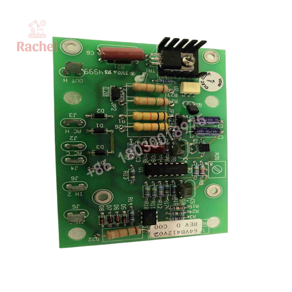
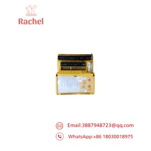
64VB412V02
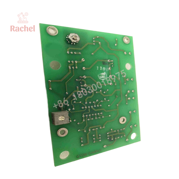
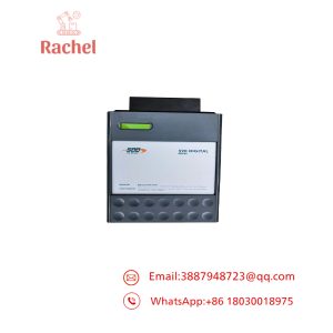
64VB412V02
Transparency SOP: Quality Assurance & Testing
We test every OLEC control board to ensure plug-and-play field performance:
- Inbound Visual Audit: Microscopic inspection of trace paths, solder joints, component alignment, and verification of zero burn marks or swelling capacitors.
- DC Voltage Rail Test: Bench check of onboard linear regulator IC outputs to confirm clean DC internal supply rails under static power.
- Sensor Input Simulation: Injecting precision millivolt/microamp reference signals to verify the linear response of the signal conditioning circuitry.
- Output Driver Validation: Activating relay drive lines and shutter trigger outputs under simulated load to confirm sharp, clean switching.
- ESD Protective Packaging: Enclosed in anti-static shielding bags and packaged in custom foam enclosures to prevent shipping damage.
The Veteran’s Tech Trap Guide
- ⚠️ Label Terminal Connections Before Removal: The wiring harness attached to the spade terminals (e.g., IN, AC, OUT headers) must be connected to their exact corresponding positions. Reversing signal and AC input lines will instantly blow the onboard amplifier ICs.
- ❗ Never Disconnect under Live Power: Turn off main power to the exposure frame and discharge high-voltage lamp capacitors before servicing this board. High-voltage transients will easily destroy sensitive CMOS components.
- ⚠️ Clean the Optical Sensor Cable: A dirty or oxidized photocell connector plug will mimic a dead 64VB412V02 card by sending zero signal to the board input. Inspect and clean the sensor cable jack with contact cleaner before replacing the card.
- ❗ Observe ESD Precautions: Always use a grounded wrist strap when handling this card. Static discharge can damage high-impedance input channels without leaving any visual trace of failure.
Frequently Asked Questions (FAQ for Conversion)
Q: Is the OLEC 64VB412V02 board hot-swappable?
A: No. You must fully isolate mains power to the exposure system before removing or installing this board to avoid electrical shock and equipment damage.
Q: Does replacing this board require recalibrating the light integrator sensor?
A: Yes. Because every photodiode sensor and control board pair has minor gain variations, you should run a standard light integrator calibration sequence using a reference UV radiometer after installation.
Q: Why buy a surplus OLEC 64VB412V02 board instead of buying a modern digital integrator system?
A: Retrofitting an existing exposure console with a completely modern digital integrator requires panel modifications, rewiring, and significant downtime. A drop-in 64VB412V02 replacement card gets your tool operating immediately at a fraction of the cost.
Q: How do you verify that this board will handle continuous production?
A: Every unit passes electrical voltage rail audits, signal simulation checks, and output load tests on our dedicated bench setups prior to inventory entry.
Q: What warranty is included with this replacement card?
A: All our reconditioned and new surplus OLEC components are backed by a full 12-month replacement warranty.

 Start Chat


