





Description
Core Product Summary
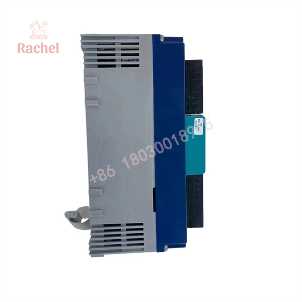
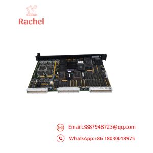
The Rolls-Royce Marine RRDIO15 is an input/output (I/O) circuit card associated with marine automation and alarm-module applications. Product listings identify it as an I/O alarm module or I/O circuit card used in Rolls-Royce Marine control equipment.
The model is intended for equipment identification and replacement planning in existing marine control installations. Exact channel configuration, electrical ratings, communication interface and terminal assignments should be verified against the installed hardware and applicable system documentation before procurement or commissioning.
Key Technical Specifications
| Parameter | Details |
|---|---|
| Brand | Rolls-Royce Marine |
| Model | RRDIO15 |
| Product type | I/O circuit card / I/O alarm module |
| System application | Marine automation and alarm systems |
| Hardware identification | RRDIO15 |
| Board revision | Verify on the physical card; Revision I appears in a product listing |
| Electrical supply | Confirm from the card label and system documentation |
| I/O channel configuration | Verify against the exact hardware revision |
| Communication interface | Confirm from host-system documentation |
| Mounting and connection details | Installation-specific; inspect the original assembly |
Engineering Selection Highlights
- Exact model matching: Confirm that the installed card is marked RRDIO15.
- Revision verification: Compare the revision and additional PCB identifiers before ordering a replacement.
- System compatibility: Confirm that the card is specified for the vessel’s existing Rolls-Royce Marine control and alarm system.
- Electrical interface: Verify supply voltage, signal types, connector assignments and permissible operating limits from technical documentation.
- Replacement planning: Check the host module, wiring arrangement and system configuration before removing or installing the card.
System Compatibility & Integration Requirements
The RRDIO15 is associated with Rolls-Royce Marine I/O alarm equipment. Compatibility should be established against the particular control-system installation rather than inferred from the model name alone.
| Integration item | Requirement |
|---|---|
| Host equipment | Confirm the supported Rolls-Royce Marine automation or alarm assembly |
| Hardware revision | Match the installed card and documented replacement revision |
| Power supply | Verify the specified voltage and polarity |
| Field signals | Confirm input/output types and channel assignments |
| Communications | Verify the interface and network requirements for the host system |
| Configuration | Follow the applicable system commissioning and maintenance procedure |
Do not assume hot-swapping, redundant operation, or compatibility with a newer platform unless the system documentation explicitly confirms it.
Dimensions, Mounting & Connection Notes
Public product information does not establish a complete mechanical drawing or definitive terminal layout for every RRDIO15 revision.
Before installation, check:
- PCB dimensions and mounting arrangement.
- Connector type, pinout and orientation.
- Supply terminals and electrical ratings.
- Board revision and any supplementary hardware identifiers.
- Required isolation, grounding and handling precautions.
Use the original equipment documentation for wiring and installation. Do not rely on visual similarity alone to establish interchangeability.
RRDIO15
Detailed Product Overview
Marine automation interface
The RRDIO15 is identified in product listings as a Rolls-Royce Marine I/O circuit card used with I/O alarm equipment. Its relevance is primarily in maintaining or servicing an existing marine automation installation where the correct hardware identity matters.
Hardware identification and replacement
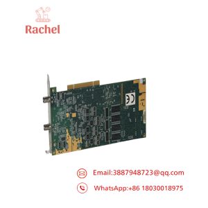
When sourcing the RRDIO15, record the full model marking, PCB revision and supplementary board identifiers from the physical card. Compare these details with the installed assembly and the equipment documentation. This reduces the risk of selecting a card with a similar designation but a different hardware configuration.
Installation and maintenance considerations
Before replacement, document the existing wiring and verify the approved isolation procedure. Confirm the supply requirements, signal interfaces and system configuration before returning equipment to service. For safety-related vessel systems, follow the applicable maintenance procedures and commissioning checks.
Applications & System Role
The RRDIO15 is associated with marine automation and alarm I/O applications. Depending on the host-system configuration, I/O alarm equipment can support the acquisition or distribution of equipment status and alarm signals.
Potential system contexts include:
- Shipboard automation and monitoring.
- Marine equipment alarm systems.
- Machinery status monitoring.
- Maintenance and replacement of installed marine control hardware.
The specific signals handled by an individual RRDIO15 installation must be confirmed from its system drawings and configuration records.
Frequently Asked Questions
1. What is the Rolls-Royce RRDIO15?
The RRDIO15 is a Rolls-Royce Marine I/O circuit card associated with I/O alarm module applications.
2. Is the RRDIO15 a digital I/O module?
Listings describe it as an I/O alarm module or circuit card. The precise input/output configuration should be confirmed against the applicable hardware revision and system documentation.
3. What voltage does the RRDIO15 require?
A definitive supply specification cannot be established from the model number alone. Check the card markings and the original equipment documentation before applying power.
4. How can I confirm compatibility with an existing system?
Compare the complete model and revision markings, host assembly, connector arrangement, electrical interface and documented system requirements.
5. Can a visually similar card replace the RRDIO15?
Not necessarily. Similar appearance does not prove electrical or functional compatibility. Confirm the approved replacement specification before installation.
6. What should be checked before ordering?
Verify the model, PCB revision, additional identifiers, connector configuration and host-system requirements. Also confirm the condition and testing status of the supplied unit.

 Start Chat


