





Description
Product Introduction and Engineering Value
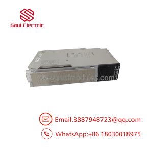
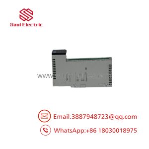
The Schneider Electric AS-B836-016 is a 16-point isolated DC output module designed for legacy Modicon 800-Series PLC installations. It supports field circuits operating from 12 to 250 VDC, with individual output channels and specified current limits for different operating voltages. This makes it suitable for maintaining established discrete-control systems without redesigning the entire I/O architecture.
For replacement projects, engineers should verify the field voltage, load current, connector, fuse arrangement, and rack compatibility. The module’s isolated output design does not eliminate the need to observe the manufacturer’s wiring and protection requirements.
Technical Specifications
| Parameter | Specification |
|---|---|
| Manufacturer | Schneider Electric / Modicon |
| Model | AS-B836-016 |
| Module category | Isolated DC output |
| Number of output points | 16 |
| Operating voltage | 12–250 VDC |
| Number of output groups | 16 |
| Outputs per group | 1 |
| Typical maximum load at 48 VDC | 1.5 A per point |
| Typical maximum load at 125 VDC | 1.0 A per point |
| Typical maximum load at 250 VDC | 0.75 A per point |
| Maximum cumulative switched current | 8 A across all channels |
| Maximum surge current | 5 A for 10 ms, at a 1-second repetition interval |
| Maximum off-state leakage | 1 mA at 12 VDC |
| Maximum on-state voltage drop | 3 V at 1.5 A |
| Maximum response time | 1 ms OFF-to-ON; 5 ms ON-to-OFF |
| Internal power requirements | +5 V at 50 mA; +4.3 V at 603 mA; −5 V at 0 mA |
| Terminal connector | AS-8535-000 |
| Fusing | One 4 A fuse per group |
| Rack space | One slot |
| Weight | Approximately 2.55 lb (1.16 kg) |
Specifications are based on the Modicon 800-Series I/O reference documentation. The per-channel current figures are voltage-dependent, and the 8 A cumulative limit still applies when multiple channels are active.
Design caution: The 250 VDC rating is not permission to operate every output at 0.75 A under every load condition. Verify the load characteristics, fuse selection, wiring insulation, and switching requirements against the complete manual before commissioning.
Field Applications and Practical Maintenance
Consider a plant maintaining an older Modicon 984 controller that operates a group of DC solenoid valves and auxiliary actuators. During a planned shutdown, one output channel fails to switch reliably. The maintenance team identifies the installed card as an AS-B836-016 and sources a replacement using the complete model number and the specified AS-8535-000 terminal connector.
Before installing the spare, the team checks the field supply voltage, individual load currents, fuse condition, and terminal assignments. Once installed, each affected output is tested under the approved maintenance procedure. The controller is returned to service only after the field devices respond correctly and the relevant interlocks are verified.
This is an illustrative maintenance scenario, not a documented incident involving a particular installation.
Other application scenarios include:
- DC solenoid control: Switching individual valve coils in legacy process-control cabinets, provided the load and suppression requirements remain within the module’s limits.
- Power-plant auxiliary equipment: Operating discrete DC control circuits for auxiliary machinery and status-dependent actuators.
- Legacy industrial sequencing: Maintaining 16-point output interfaces in established Modicon 800-Series and compatible 984 I/O configurations.
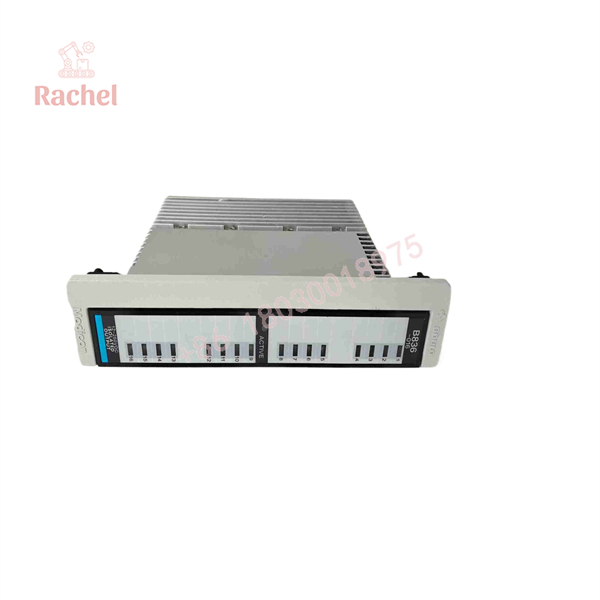
AS-B836-016
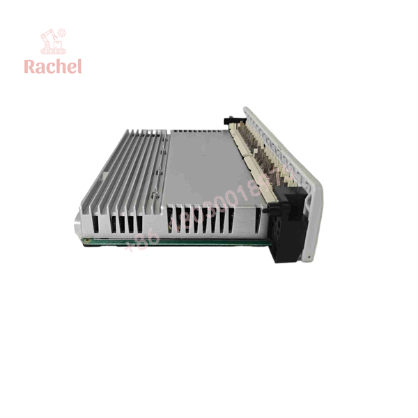
AS-B836-016
Quality Assurance and Testing
For new-surplus or refurbished inventory, require evidence that the module has been inspected and tested rather than relying solely on its physical appearance.
- Identity verification: Check the full AS-B836-016 designation, manufacturer markings, and available serial or traceability information.
- Visual inspection: Examine the board, terminal connector, fuse holders, and accessible components for corrosion, heat damage, cracked solder joints, or unauthorized repairs.
- Electrical testing: Confirm that the test setup uses an appropriate DC supply and stays within the documented voltage and current limits.
- Channel-by-channel functional test: Exercise all 16 outputs and record switching behavior, off-state leakage, and on-state voltage drop where the test procedure supports those measurements.
- Final report: Request test results, condition classification, any repair history, and written warranty terms.
A new-surplus unit may have been stored for years, and unused status does not prove present-day functionality. For refurbished stock, request the specific tests performed and any channels or operating conditions that were not covered.
Replacement Pitfalls: What to Check Before Power-Up
1. Exceeding the cumulative current limit
Each output’s allowable load depends on the operating voltage, but the module also has an 8 A total switched-current limit. Sixteen individually acceptable loads can still exceed the aggregate rating when operating simultaneously.
2. Ignoring the voltage drop across the output
The specified on-state voltage drop can reach 3 V at 1.5 A. For a DC load operating near its minimum acceptable voltage, calculate the voltage available at the load rather than assuming it will receive the full supply voltage.
3. Treating every 800-Series output module as interchangeable
The AS-B836-016 is an isolated DC output module, not a generic 24 VDC output card. Verify the replacement’s voltage range, terminal connector, backplane requirements, and channel configuration. Also check the original fuse arrangement before energizing the field wiring.
Frequently Asked Questions
Q1. What is the Schneider Electric AS-B836-016 used for?
It provides 16 isolated DC output points for compatible legacy Modicon 800-Series I/O systems. It is used to switch field circuits in industrial control applications.
Q2. Does the AS- support 24 VDC loads?
Yes. Its documented operating range is 12–250 VDC, which includes 24 VDC. The current draw, load characteristics, and aggregate output current must still remain within the module’s limits.
Q3. Can all 16 outputs operate at their maximum individual current simultaneously?
Not necessarily. The maximum cumulative switched current is 8 A across all channels. The individual channel ratings and total module limit must both be satisfied.
Q4. Which terminal connector does this module use?
The documented connector is AS-8535-000. Confirm that the installed terminal assembly and wiring match the original system documentation before fitting a replacement.
Q5. Is new-surplus or refurbished stock available?
The AS- appears in industrial spare-parts and repair-service catalogs. Actual stock, condition, and lead time must be confirmed directly with the supplier.
Q6. How should buyers verify authenticity and warranty coverage?
Request photographs of the actual unit and its nameplate, traceability information where available, a channel-level functional-test report, and written warranty terms. Confirm whether the warranty is provided by the reseller or the manufacturer; do not assume that new-surplus status establishes either authenticity or operational condition.

 Start Chat


