





Description
Product Introduction & Engineering Value
The IM483-PLG is a compact stepper-motor drive intended for applications requiring controlled current regulation and microstepping from a relatively small electronics package. Its 12–48 VDC supply range and up to 4 A phase-current capability make it suitable for machine axes, positioning mechanisms, and other discrete-motion applications.
The -PLG suffix is important. It identifies the locking pluggable terminal configuration, rather than a different motor-control algorithm. The manufacturer specifically notes that this version is pin-compatible with the IM804/5-PLG, allowing a straightforward hardware swap where higher motor power is subsequently required.
Technical Specifications
| Parameter | IM483-PLG |
|---|---|
| Manufacturer | Intelligent Motion Systems / Schneider Electric |
| Model | IM483-PLG |
| Drive Type | High-performance microstepping driver |
| Motor Type | Two-phase stepping motor |
| Input Voltage | +12 to +48 VDC ±10% |
| Phase Output Current | 0.4–4 A peak/current-control range |
| Typical RMS Current Rating | Up to approximately 3 A |
| Step Input | Isolated |
| Direction Input | Isolated |
| Enable Input | Isolated |
| Reset Input | Isolated |
| Maximum Input Switching Rate | Up to 10 MHz |
| Connector Configuration | Two 8-position pluggable interfaces |
| Mating Connector | PLG-R1 / PLG-R2 |
| Operating Temperature | 0 to +70 °C for the -PLG configuration listing |
| Storage Temperature | -40 to +125 °C |
| PCB Dimensions | Approx. 2.75 × 3.00 in |
| Board Thickness | Approx. 0.03 in |
The original IM483 documentation gives the electrical input range as 12 to 48 VDC, with a nominal 3 A RMS and 4 A peak phase-current specification under its stated test conditions.
Connector Configuration
This is where the model designation earns its keep.
The standard IM483 has multiple connector variants, including -34P1, -8P2, -34P1-8P2, and -PLG. The -PLG version replaces the standard P1/P2 arrangements with two 8-position pluggable interfaces.
The optional mating terminal set is identified as PLG-R, with separate P1 and P2 replacement terminal designations PLG-R2 and PLG-R1.
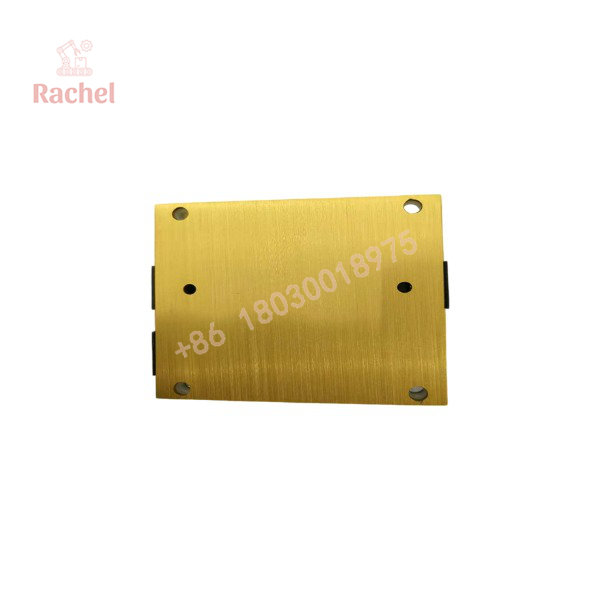
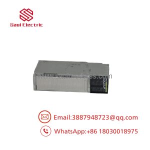
IM483-PLG
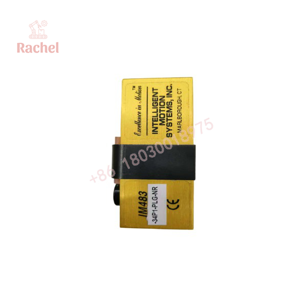
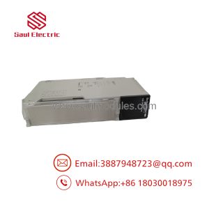
IM483-PLG
Field Application & the “Trench” Experience
A common legacy-machine failure is deceptively simple: the stepper motor still has power, the controller is generating pulses, but one axis no longer moves correctly. The temptation is to replace the motor first.
That can be the wrong move.
With an IM483 installation, the current-adjustment network, motor inductance, supply voltage, wiring, and driver configuration all affect whether the axis operates correctly. The IM483 documentation specifically states that a current-adjustment resistor is required for operation.
A realistic replacement scenario would involve a packaging machine where the indexing axis uses an IM483-PLG. The original driver develops an intermittent fault. A replacement driver is installed, but the technician discovers that the existing current-adjust resistor and motor wiring must be retained and checked against the new unit’s configuration before returning the axis to service.
Niche applications include:
- Packaging-machine indexing and registration axes
- Labeling-machine feed mechanisms
- Small CNC positioning axes
- Automated inspection fixture positioning
- Rotary indexing tables and actuator mechanisms
Transparency SOP: QA & Testing
For New Surplus or Refurbished -PLG inventory, testing should focus on the driver electronics and connector configuration.
1. Physical inspection
Check the PCB, power terminals, locking connectors, mounting holes, heat-transfer surfaces, and component condition. Pay particular attention to signs of overheating around the power stage.
2. Supply test
Apply a controlled DC supply within the specified 12–48 VDC range. Verify normal startup current and absence of abnormal heating.
3. Logic-input test
Test the isolated:
- Step/clock input
- Direction input
- Enable input
- Reset input
The driver should respond consistently to the appropriate control signals.
4. Motor-load test
Connect a compatible stepper motor and verify:
- Correct phase operation
- Direction reversal
- Microstep operation
- Current regulation
- Enable/disable behavior
- Fault response
5. Thermal test
Operate the driver under representative motor load and monitor temperature. A driver that passes a five-minute no-load test has not necessarily passed a meaningful acceptance test.
The Veteran’s Tech Trap Guide
⚠️ Trap #1 — Getting the connector variant wrong.
, IM483-8P2, IM483-34P1, and -PLG are related products, but their connector arrangements are different. The -PLG specifically uses pluggable interfaces at P1 and P2.
⚠️ Trap #2 — Forgetting the current-adjustment resistor.
This is a real commissioning issue. The manufacturer’s quick-reference documentation states that a current adjustment resistor is required to operate the IMx driver. Do not simply reconnect the motor and assume the drive will automatically establish the correct phase current.
⚠️ Trap #3 — Running the wrong motor inductance.
The IM483 has specified acceptable motor inductance characteristics. A motor that physically connects to the driver is not necessarily an electrically suitable motor. The documentation provides inductance guidance for different supply conditions.
PRO TIP: Photograph the existing driver’s resistor settings and both P1/P2 connectors before removal. For legacy motion equipment, that photograph can be more useful than the part number alone.
Dynamic FAQ
What is the Schneider IM483-PLG?
It is a high-performance microstepping driver from the Intelligent Motion Systems IM483 family, sold under Schneider Electric’s motion-control product lineage. It is designed to control two-phase stepping motors.
What voltage does the IM483-PLG require?
The IM483 operates from +12 to +48 VDC ±10%. The supply should be appropriately sized for the motor current and application.
What is the maximum motor current?
The published electrical specifications identify approximately 3 A RMS and 4 A peak phase-current capability under the stated test conditions.
What does the PLG suffix mean?
-PLG identifies the pluggable terminal configuration. Both P1 and P2 use 8-position pluggable interfaces, with optional removable mating screw-terminal sets.
Is IM483-PLG discontinued?
Yes. Current industrial spare-parts listings identify the IM483-PLG as discontinued by the manufacturer.
Is New Surplus IM483-PLG acceptable?
Yes, assuming the unit is genuinely unused and has been stored correctly. Because this is an older motion-control product, I would still recommend functional testing of the power stage, isolated inputs, current regulation, and motor output before installation.
What warranty should I request?
For New Surplus or refurbished stock, request coverage for power-up, step/direction response, enable/reset operation, phase-current regulation, motor operation, and connector integrity. A visual inspection alone is not sufficient for a stepper-motor driver.

 Start Chat


