





Description
Product Introduction
The SKF CMPT CTU Copperhead Transmitter Unit is a digital vibration and temperature transmitter used in continuous machinery condition monitoring. It accepts compatible industrial accelerometer signals, processes vibration data using selectable acceleration, velocity, or acceleration-enveloping analysis, and supplies analog outputs to PLCs, DCS platforms, and compatible SKF monitoring equipment.
Its practical advantage is local signal processing without requiring a dedicated vibration analysis rack. Engineers can configure measurement ranges and signal averaging through front-panel rotary switches, while 4–20 mA or 0–10 VDC outputs provide straightforward integration with existing control systems. It is particularly useful for monitoring bearing condition, mechanical looseness, imbalance, and other changes in rotating machinery vibration.
Key Technical Specifications
| Parameter | Specification |
|---|---|
| Manufacturer | SKF |
| Product Family | Copperhead |
| Model | CMPT CTU |
| Part Number | 32163100, as listed in the instruction manual |
| Product Type | Digital vibration and temperature transmitter |
| Power Supply | 24 VDC nominal; operating range 22–28 VDC |
| Maximum Supply Current | 250 mA |
| Power Consumption | 6 W maximum |
| Sensor Compatibility | Constant-current accelerometers, typically 10, 30, 100, or 230 mV/g |
| Vibration Analysis | Acceleration, velocity, and acceleration enveloping |
| Acceleration Frequency Range | 3 Hz–10 kHz for RMS and peak-hold modes |
| Velocity Frequency Range | 10 Hz–1 kHz or 2 Hz–1 kHz, depending on the selected mode |
| Acceleration Enveloping Range | 500 Hz–10 kHz, filter band 3 |
| Vibration Output | 4–20 mA or 0–10 VDC |
| Temperature Output | 4–20 mA or 0–10 VDC; scaled for 0–120°C |
| Communication | CAN bus using SKF’s protocol |
| Mounting | 35 mm DIN rail, EN 50022 |
| Operating Temperature | 0°C to +70°C |
| Protection Rating | IP20 |
| Dimensions | 75 × 45 × 118 mm (H × W × D) |
| Weight | Approximately 225 g |
Source: SKF’s published CMPT CTU technical specification.
Important compatibility limitation: The CTU is not a universal accelerometer interface. SKF specifically excludes the CMSS 793T and CMSS 797T sensors because of differences in temperature-sensor power requirements. Verify the sensor model, sensitivity, wiring, and output scaling before installation.
Application Scenarios & The “Trench” Experience
A production line begins reporting elevated vibration on a critical pump. The PLC still runs normally, but its analog input shows a steady value that does not match handheld vibration measurements. The problem could be the accelerometer, transmitter configuration, output scaling, or PLC input setup. Replacing the CTU without checking those four items can waste a maintenance window.
The CMPT CTU is suited to applications where vibration measurements need to reach an existing automation system without a separate high-end monitoring rack.
- Mining and Cement — Kilns and Roller Presses — Acceleration-enveloping analysis can help identify repetitive impact signatures and bearing defects, including on low-speed machinery.
- Oil and Gas — Pumps and Compressors — Velocity and acceleration outputs provide continuous vibration measurements for PLC/DCS trending and alarm handling.
- Power Generation — Auxiliary Rotating Equipment — Supports continuous monitoring of vibration and optional bearing or sensor temperature signals where the selected sensor provides temperature measurement.
- Manufacturing — Motors and Fans — Provides analog vibration signals for plant alarm systems and maintenance trending.
- Heavy Industry — Legacy Machinery Monitoring — Offers a retrofit path when a plant needs continuous vibration monitoring using existing analog input cards.
These applications reflect documented CTU capabilities; the required analysis mode, sensor, and measurement range must be selected for each machine.
Illustrative field case study
A cement plant experiences intermittent high-vibration alarms on a slow-speed roller press. The maintenance team initially suspects a failing transmitter because the PLC trend fluctuates sharply.
The engineers check the accelerometer sensitivity, CTU function and range switches, and PLC scaling. They discover that the transmitter is configured for a different measurement range than the control-system engineering assumes. The team corrects the configuration under the approved maintenance procedure and verifies the 4–20 mA output against a known test input.
The lesson is simple: verify the measurement chain before condemning the transmitter. A sensor, configuration, or scaling fault can produce symptoms that look like hardware failure.
This is a hypothetical example, not a documented customer case.
Transparency SOP: Quality Assurance & Testing
A used or surplus transmitter should be evaluated against its intended measurement function, not merely whether its power indicator turns on.
1. Inbound Inspection
- Record the part number, serial number, and available revision information.
- Inspect the enclosure, terminal blocks, rotary switches, BNC connector, and labels.
- Document the actual condition: new surplus, factory sealed, used, or refurbished.
2. Live Functional Testing
- Apply a controlled 24 VDC supply within the documented operating range.
- Check the sensor-status indicator and available fault indications.
- Use an appropriate accelerometer simulator or calibrated signal source to verify measurement response.
- Confirm that the selected vibration mode produces the expected output.
3. Electrical Output Checks
- Verify the 4–20 mA and/or 0–10 VDC output, as applicable.
- Check the temperature channel if the unit and test setup support it.
- Confirm output scaling at representative points rather than testing only one value.
- Do not apply insulation-resistance test voltages to electronic circuitry unless explicitly authorized by the OEM.
4. Configuration and Communication Verification
- Record the FUNCTION and RANGE switch positions.
- Confirm the expected accelerometer sensitivity and full-scale range.
- Where CAN-bus operation is required, verify addressing, wiring, termination, and communication with compatible equipment.
5. Final QC and ESD Packaging
- Record the test results and inspection date.
- Protect the unit from electrostatic discharge and mechanical damage.
- Supply available test documentation and written warranty terms.
Procurement note: Request a test report tied to the actual unit being shipped. If the supplier only performs a power-on check, that should be described as a power-on check—not a full functional test.
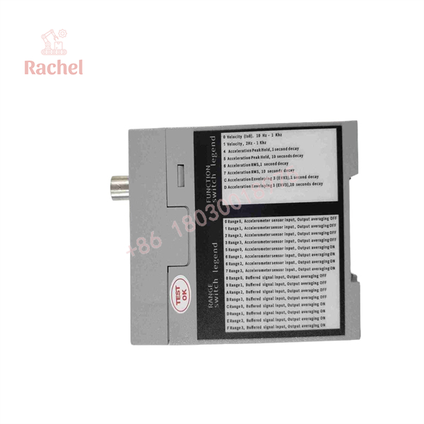
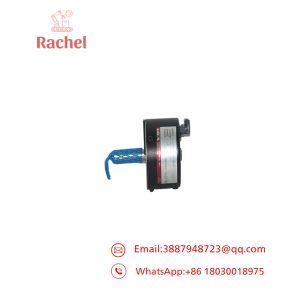
CMPT CTU
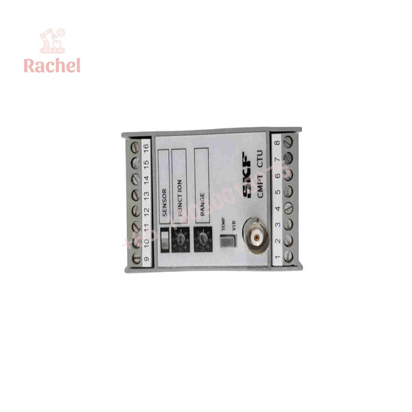
CMPT CTU
The Veteran’s Tech Trap Guide
Warning 1: The rotary switches define the measurement.
The FUNCTION switch selects the vibration analysis mode, while the RANGE switch determines the measurement range and can enable output averaging. Photograph both switch positions before removing the unit. Copying the wiring alone will not preserve the original configuration.
Warning 2: Verify the PLC scaling.
A 4–20 mA signal represents the configured full-scale measurement, not a universal vibration range. If the transmitter is set for 0–30 mm/s but the PLC interprets the signal as 0–15 mm/s, the displayed value will be wrong even when the transmitter works correctly.
Warning 3: Check sensor compatibility and cable shielding.
Confirm the accelerometer’s sensitivity and whether its integrated temperature sensor is compatible with the CTU. Follow the OEM wiring instructions for the sensor return, shield, and grounding arrangement. Poor shielding or incorrect grounding can introduce misleading vibration readings.
Warning 4: CAN bus is not Modbus TCP.
The CTU uses SKF’s documented CAN protocol for communication among supported devices. Do not connect it to a generic Ethernet switch and expect standard industrial Ethernet communications. Check the required interface hardware, addressing, and bus termination.
Frequently Asked Questions (FAQ for Conversion)
Q1. Is the SKF CMPT CTU hot-swappable?
Do not treat it as a hot-swappable PLC card. It is a separately powered, DIN-rail-mounted transmitter. Follow the site isolation procedure, remove power as required, and verify the wiring before replacement.
Q2. Can the CMPT CTU connect directly to a PLC or DCS?
Yes. Its processed vibration and optional temperature outputs can be configured for 4–20 mA or 0–10 VDC, subject to the selected mode and wiring. Confirm that the receiving analog input supports the chosen signal type and range.
Q3. Does the CMPT CTU support Modbus RTU or Modbus TCP?
The documented communication interface is CAN bus using SKF’s protocol. Its standard analog outputs are the more direct integration path for a conventional PLC/DCS. Do not assume Modbus support without an explicitly documented compatible interface.
Q4. Can one CTU monitor both vibration and temperature?
Yes, when used with a compatible accelerometer that includes an integrated temperature sensor. Vibration and temperature have separate output connections. The temperature output is scaled for 0–120°C in the published specifications.
Q5. Can I use any industrial accelerometer with this transmitter?
No. The sensor must meet the electrical and sensitivity requirements, and integrated temperature sensing must be compatible if temperature monitoring is required. The OEM lists supported sensor families and explicitly excludes certain models. Check the exact sensor part number before connecting it.
Q6. Why is a surplus CMPT CTU cheaper than buying through an OEM channel?
Surplus stock may come from plant closures, unused maintenance inventory, or secondary-market suppliers. Pricing can be lower, but the unit may have less traceable service history or a different warranty arrangement. Compare the actual condition, functional test evidence, return policy, and warranty rather than price alone.
Q7. How can I tell whether the unit is genuine or refurbished?
Request actual photographs, the part and serial numbers, and any available provenance or test documentation. Inspect the enclosure and terminals for evidence of use or repair. Original packaging does not prove that a unit is unused, and refurbished does not automatically mean counterfeit. The seller should disclose the condition in writing.

 Start Chat


