





Description
Product Introduction & Engineering Value
The GE Multilin SR469-P1-HI-A20-T is a digital motor protection relay engineered for medium-voltage electric motors across heavy industrial process applications. It provides comprehensive thermal model protection, mechanical overload sensing, stator/bearing RTD temperature monitoring, and fault detection for medium and large induction motors.
By combining primary protection functions (ANSI 49, 50/51, 50G/51G, 86, 37, 46) with deep motor diagnostics, the 469 eliminates individual single-function relays. The T suffix indicates factory conformal coating on internal printed circuit board stacks, protecting delicate microprocessors from corrosive gases (such as H_2S and SO_2), moisture, and particulate buildup in severe chemical, mining, or marine environments.
Part Number Decoder & Hardware Specs
Order Code Breakdown: SR469 - P1 - HI - A20 - T
SR469: Base Model (Multilin 469 Motor Management System)P1: Phase Current Inputs — 1A CT Secondaries (Requires 1A CT loop design)HI: Power Supply — 90–300 VDC / 70–265 VAC high-voltage control busA20: Analog Output Card — 4x 4–20 mA (or 0–20 mA / 0–1 mA) assignable outputsT: Option — Test / Conformal Coated PCBs for harsh ambient locations
Technical Specifications
- Thermal Model: Thermal capacity used calculation incorporating overload curve, stator RTD feedback, RTD bias, and unbalance current heating factor
- RTD Inputs: 12 3-wire RTD inputs (100-ohm Platinum, 120-ohm Nickel, 100-ohm Nickel, or 10-ohm Copper)
- Digital Inputs: 9 assignable optical inputs for emergency stop, local reset, or status tracking
- Output Contacts: 4 Form-C and 2 Form-A output relays (Trip, Alarm, Auxiliary, Block Start)
- Communications: 2x Rear RS485 Modbus RTU ports + 1x Front RS232 programming port
- Enclosure: 3/8-size draw-out case with automatic CT shorting mechanism
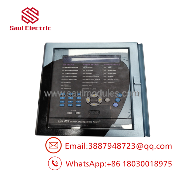
- SR469-P1-HI-A20-T
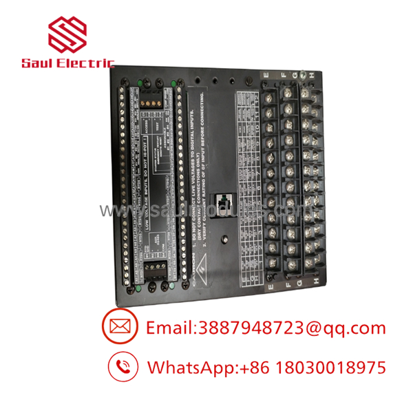
- SR469-P1-HI-A20-T
Field Application & The “Trench” Experience
During a reliability upgrade at a wastewater treatment facility, engineers encountered frequent relay component failures on two 4.16kV aeration blower motors due to hydrogen sulfide (H_2S) gas vapor seeping into the local electrical house. The existing relays suffered copper mirror corrosion on the internal memory buses.
The plant specified the SR469-P1-HI-A20-T as the replacement. Equipped with factory conformal coating (T option), the unit resisted sulfur degradation. Operating on 1A phase CTs (P1) and powered directly from the station’s 125V DC battery bank (HI), the relay routed motor thermal capacity, running currents, and bearing temperatures back to the central SCADA system using its 4–20 mA analog outputs (A20).
Niche Application Scenarios:
- MV Induction Motors in Corrosive Plants: Protection of paper mill, refinery, and chemical plant drive motors exposed to atmospheric contaminants.
- Large Water Pump Drives: Managing start-inhibit logic and thermal capacity calculations for municipal high-lift pumps.
- Ball Mill & Crusher Motors: Monitoring high-inertia starts with custom acceleration thermal limit curves.
Transparency SOP: QA & Testing
- Draw-Out Latch & Contact Inspection: The outer chassis fingers, draw-out latching handles, and rear spring-loaded CT shorting bars are verified for zero corrosion or physical wear.
- Conformal Coating Integrity Check: Internal circuit boards are inspected under UV light to confirm uniform conformal coating coverage over all surface-mount ICs.
- Power Supply High-Voltage Ramp: The
HIpower supply is energized at 70 VAC, 120 VAC, 240 VAC, and 125 VDC to confirm stable bootup and power supply regulation. - 1A Phase Current Injection: Precision 1A secondary currents are applied across all phase channels using a three-phase test set to calibrate metering accuracy within ±0.5% of full scale.
- Analog Output Loop Test: Current meters are connected to all 4 analog output channels (
A20) while forcing software test values to confirm accurate 4–20 mA output response.
The Veteran’s Tech Trap Guide
- ⚠️ CT Input Matching (
P1vs.P5): This model strictly requires 1A secondary CTs. Wiring a 5A secondary CT circuit into aP1relay will inject 5x the expected current into the internal sensing transformers, causing immediate false trips or internal component damage. - PRO TIP (Difference Between
TandEOptions): TheTsuffix signifies conformal coating / factory test processing, whereas theEsuffix indicates an Enhanced front panel display. If replacing an existingEmodel with aTmodel, confirm display preferences with site operators. - ⚠️ 10-Ohm Copper RTD Wiring Resistance: If using 10-ohm copper RTDs for motor winding temperature monitoring, ensure lead resistance is balanced across all three wires. Because 10-ohm RTDs have a low resistance change per degree, lead imbalance will cause large temperature reading errors.
Dynamic FAQ
Q: What does the T option stand for in the part number SR469-P1-HI-A20-T?
A: The T option denotes Test / Conformal Coated printed circuit boards, which protect internal electronics from moisture, dust, and corrosive airborne contaminants.
Q: What power supply voltage range does the HI power supply option accept?
A: The HI option operates across 90 to 300 VDC or 70 to 265 VAC, making it compatible with standard station battery banks and AC control transformers.
Q: Can I use this relay with 5A CT secondaries?
A: No. The P1 code specifies 1A secondary current inputs. If your installation uses 5A CT secondaries, you must select an SR469-P5-... model or install interposing 5A-to-1A matching transformers.



 Start Chat


