





Description
Product Introduction & Engineering Value
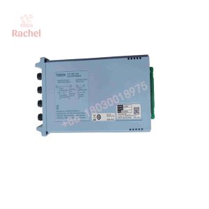
The Yokogawa AAI143-S50 is intended for process-control applications where multiple 4–20 mA transmitter loops need isolated analog acquisition. It provides 16 isolated inputs, supports both 2-wire and 4-wire transmitter configurations on a per-channel basis, and can be deployed in dual-redundant configurations within the supported Yokogawa I/O architecture.
The key distinction from the AAI141 family is the isolation architecture. AAI143 is specified as an isolated analog input module, making the exact model important when replacing an existing card in a cabinet with field-to-system isolation requirements.
Technical Specifications
| Specification | AAI143-S50 |
|---|---|
| Manufacturer | Yokogawa Electric Corporation |
| Model | AAI143 |
| Ordering Code | AAI143-S50 |
| Input Type | Analog current input |
| Input Range | 4–20 mA DC |
| Input Channels | 16 |
| Input Isolation | Isolated |
| Allowable Input Current | 24 mA |
| Input Resistance, Power ON | 270 Ω at 20 mA to 350 Ω at 4 mA |
| Input Resistance, Power OFF | 500 kΩ or higher |
| Accuracy | ±16 µA |
| Data Update Period | 10 ms |
| Isolation Withstand Voltage | 1500 VAC for 1 minute |
| Transmitter Supply | ≥19.0 V at 20 mA; ≤25.5 V at 0 mA |
| Transmitter Supply Limit | 25 mA |
| 2-Wire / 4-Wire Transmitter | Selectable per channel |
| Maximum Current Consumption | 230 mA at 5 VDC; 540 mA at 24 VDC |
| Approx. Weight | 0.3 kg |
| Redundancy | Dual-redundant configuration supported |
These values are consistent with Yokogawa’s published specifications for AAI143.
Ordering-code breakdown
AAI143-S50
- — 4–20 mA, 16-channel isolated analog input module
- S — Standard type
- 5 — No explosion protection
- 0 — Basic type
Yokogawa’s model table also defines -H as the HART version and E as the explosion-protected version. Therefore, the S50 configuration should not be described as HART-enabled or explosion-protected.
Available connection configurations
AAI143 can be ordered with different field-connection options, including:
/K4A00— KS Cable Interface Adapter, ATK4A-00/A4S00— Pressure Clamp Terminal Block, ATA4S-00/A4S10— Pressure Clamp Terminal Block with surge absorber/A4D00— Dual Pressure Clamp Terminal Block/A4D10— Dual Pressure Clamp Terminal Block with surge absorber/CCC01— Connector cover for MIL cable
These are option codes and should be matched to the existing cabinet wiring arrangement.
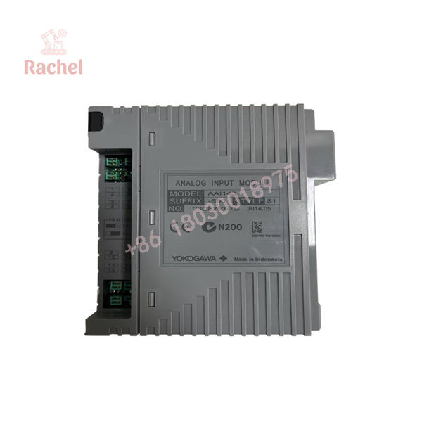
AAI143-S50
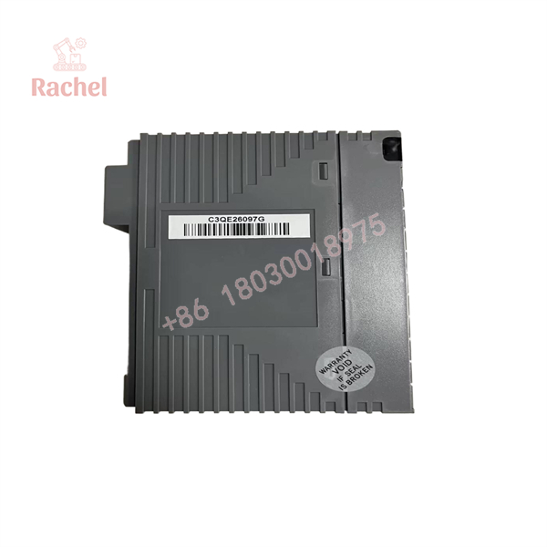
AAI143-S50
Field Application & Practical Engineering Scenario
A typical AAI143-S50 installation has a Yokogawa control cabinet receiving numerous conventional 4–20 mA process transmitter signals. The module can acquire signals from pressure, flow, level, temperature, and other analog transmitters while maintaining the specified isolation between field inputs and the system side.
Practical scenarios
Process transmitter concentration
Sixteen input channels allow multiple continuous measurements to be handled by one analog-input module.
Legacy CENTUM VP maintenance
The module is suitable for maintenance programs where existing Yokogawa FIO hardware remains in service and the installed card must be replaced without changing the I/O architecture.
Electrically separated measurement loops
The isolated input architecture is useful when the control system requires isolation between field signal circuits and system electronics.
Redundant control configurations
Yokogawa documents AAI143 as capable of operation in a dual-redundant configuration.
QA & Testing SOP
For a New Surplus or refurbished AAI143-S50, the inspection should focus on both electrical performance and the exact ordering configuration.
1. Identity verification
Confirm the label shows:
If the module has an additional option code, record the complete code.
2. Physical inspection
Inspect:
- Yokogawa label
- Front-panel condition
- Backplane connector
- PCB and enclosure
- Terminal/interface hardware
- Mounting points
- Corrosion or contamination
- Evidence of previous repair
3. 4–20 mA simulation
Use a calibrated current source to apply representative input signals, such as 4 mA, 12 mA, and 20 mA, to selected channels.
Verify that the FCS or approved test equipment reports the corresponding input values.
4. Multi-channel testing
Do not qualify a 16-channel module by testing only one channel. Test representative channels across the card and investigate any abnormal channel deviation.
5. Isolation verification
Where appropriate test equipment is available, verify the isolation characteristics according to the applicable Yokogawa maintenance procedure. The published module specification gives a 1500 VAC / 1 minute withstand value between input and system.
6. Transmitter-power test
For 2-wire transmitter applications, verify the module’s transmitter supply behavior under a controlled load. Yokogawa specifies a supply of at least 19.0 V at 20 mA and an output-current limit of 25 mA.
7. System-level test
After installation, verify:
- Correct slot recognition
- Correct channel configuration
- Stable 4–20 mA readings
- Correct transmitter configuration
- No diagnostic alarms
- Correct redundant operation where applicable
New Surplus authenticity
A New Surplus AAI143-S50 should be unused original Yokogawa hardware, not a newly manufactured generic replacement. Request photographs of the actual unit’s label and connector before purchase.
Veteran’s Tech Trap Guide
⚠️ Trap 1: Confusing S50 with H50
This is the most important ordering-code issue.
- = standard configuration
- -H50 = HART configuration
The -H suffix is what identifies the HART version. Do not assume HART functionality simply because the module is an AAI143.
PRO TIP: Match the entire part number printed on the installed module.
⚠️ Trap 2: Assuming “5” means explosion protection
It means the opposite.
Yokogawa defines:
- 5 = no explosion protection
- E = explosion protection
Do not use an S50 module as a substitute in a hazardous-area application without confirming the complete system design and certification requirements.
⚠️ Trap 3: Replacing AAI141 with AAI143 without checking the system design
Both families handle 4–20 mA signals, but AAI141 is non-isolated, while AAI143 is isolated. The electrical architecture and required terminal configuration must be checked before substitution.
⚠️ Trap 4: Ignoring the terminal option
An AAI143-S50 without the correct connection arrangement may not be a practical replacement for a cabinet using a specific terminal board or cable interface.
Check whether the installed system uses ATA4S, ATA4D, ATK4A, or another documented connection arrangement before ordering.
Dynamic FAQ
Q1. What is Yokogawa AAI143-S50?
is a 16-channel isolated analog input module for 4–20 mA signals, configured as the standard, non-explosion-protected basic version.
Q2. How many inputs does AAI143-S50 have?
It provides 16 isolated analog input channels for 4–20 mA signals.
Is isolated?
Yes. Yokogawa specifies AAI143 as a 16-channel isolated analog input module, with 1500 VAC withstand capability between the input and system side for one minute.
Q4. Does AAI143-S50 support HART?
The S50 configuration is the standard type. Yokogawa designates the -H suffix for the HART version. Therefore, HART should not be assumed for an AAI143-S50 module.
Q5. Can AAI143-S50 power a 2-wire transmitter?
Yes. The module supports 2-wire transmitter operation and provides transmitter power. The channel can also be configured for a 4-wire transmitter using the applicable setting-pin configuration.
Q6. What is the accuracy of AAI143-S50?
The published specification is ±16 µA, with a 10 ms data-update period.
Q7. Can AAI143-S50 be used in a redundant configuration?
Yes. Yokogawa documents AAI143 as supporting dual-redundant configuration. The actual redundancy architecture must still match the installed FIO system and engineering configuration.
Q8. What does the “50” in AAI143-S50 mean?
The code breaks down as:
- S = Standard type
- 5 = No explosion protection
- 0 = Basic type
This is part of Yokogawa’s published model and suffix coding.
Q9. How should New Surplus AAI143-S50 authenticity be checked?
Request photographs of the actual Yokogawa module, including the full AAI143-S50 label, serial/identification markings, connectors, and physical condition. For an exact replacement, also verify the terminal option and installed I/O architecture.
Q10. What warranty should be expected?
Warranty depends on the supplier and stock condition. Secondary-market suppliers may provide their own warranty rather than the original manufacturer’s warranty. Confirm the warranty period, DOA coverage, testing status, and return terms for the exact AAI143-S50 unit before purchase.

 Start Chat


