





Description
Product Introduction & Engineering Value
The Yokogawa AIP571 is not a conventional analog I/O card or modern Ethernet communication module. It is an electrical transceiver used in Yokogawa Vnet repeater equipment, where it works with the AIP171 controller and appropriate Vnet connector assemblies to extend an existing Vnet segment.
When the unit is marked BUS1, that designation identifies its position in the first network path of a redundant repeater arrangement. Yokogawa’s documentation shows separate BUS1 and BUS2 paths and specifies two AIP571 units for the dual-redundant configuration.
Technical Specifications
| Parameter | AIP571 BUS1 |
|---|---|
| Manufacturer | Yokogawa Electric Corporation |
| Model | AIP571 |
| Bus Designation | BUS1 |
| Function | Electrical transceiver |
| Application | Vnet repeater |
| Network Type | Yokogawa Vnet |
| Redundancy | Dual-redundant Vnet configuration |
| Controller | AIP171 |
| Optical Transceiver Options | AIP578 / AIP591 |
| 10BASE-2 Connector | S9764UK |
| 10BASE-5 Connector | S9628UK |
| Repeater Arrangement | Two transceiver units for dual-redundant configuration |
Yokogawa’s communication-device manual specifically lists AIP571 as the Electrical Transceiver, while AIP171 is the transceiver control unit. The same documentation identifies S9764UK for 10BASE-2 and S9628UK for 10BASE-5 connections.
The AIP571 is also included in Yokogawa’s certification documentation as an “Electrical Transceiver Control Unit for Vnet Repeater,” confirming its role in the Vnet repeater architecture.
Important specification clarification
There are online listings that describe AIP571 as a modern analog-input module or assign it specifications such as 16 analog channels and 16-bit resolution. Those descriptions conflict with Yokogawa’s own documentation. The manufacturer’s documentation identifies AIP571 as a Vnet repeater electrical transceiver, not an analog input module.
For procurement, the Yokogawa documentation should take precedence over generic marketplace specifications.
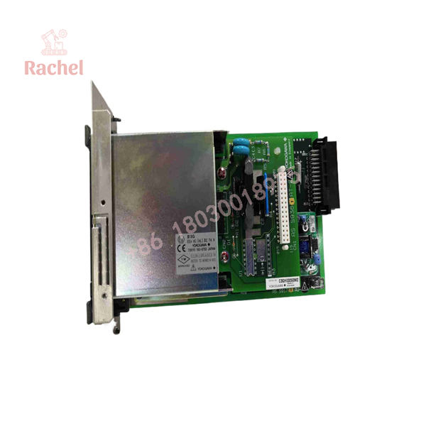
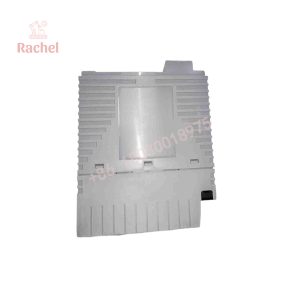
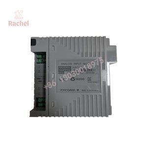
AIP571 BUS1
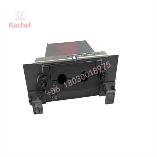
AIP571 BUS1
Field Application & the “Trench” Experience
A typical legacy-system problem is straightforward: an old Yokogawa Vnet segment has been operating for years, and one communication path begins showing faults. The plant cannot simply replace the AIP571 with a current Ethernet switch because the repeater is part of the original Vnet architecture.
For a BUS1 AIP571 replacement, the maintenance engineer needs to identify the complete repeater assembly: AIP571, AIP171 controller, power-supply unit, connector assembly, and the corresponding BUS1/BUS2 arrangement. Yokogawa documentation explicitly shows these units as components of the Vnet repeater system.
Specific application scenarios
- Legacy CENTUM Vnet control-network extension where an electrical Vnet segment must be extended beyond the normal cable distance.
- Dual-redundant Vnet repeater installation with independent BUS1 and BUS2 communication paths.
- Long-distance plant control-network sections using optical transceivers such as AIP578 or AIP591 with electrical Vnet interfaces.
- Brownfield DCS maintenance where replacing the existing communication architecture is not practical during an outage.
Yokogawa’s documentation describes repeater configurations using AIP571 together with optical transceivers and gives separate repeater arrangements for Vnet 10BASE-2 and 10BASE-5 networks.
Transparency SOP: QA & Testing
For New Surplus or refurbished AIP571 BUS1 stock, the testing procedure should focus on communication hardware rather than analog I/O.
- Part-number inspection — Confirm the AIP571 designation, nameplate, serial number, and hardware revision.
- Physical inspection — Check the board, connector interfaces, mounting points, labels, and signs of corrosion or previous overheating.
- Connector verification — Confirm compatibility with the installed Vnet connector assembly, particularly S9764UK or S9628UK as applicable.
- System-level power check — Verify correct installation in the designated repeater assembly.
- BUS1 communication test — Connect the unit to an appropriate Vnet test configuration and verify transmit/receive activity.
- Redundancy test — Where the complete dual-bus test environment is available, verify the BUS1/BUS2 arrangement and communication behavior.
- Status verification — Check the associated AIP171 controller and repeater diagnostics for communication faults.
Because the AIP571 is a legacy Vnet communication component, a simple “power-on” test is not sufficient evidence of communication functionality.
The Veteran’s Tech Trap Guide
⚠️ Trap #1 — Buying the wrong AIP571 because the listing calls it an analog module.
This is the most important issue with this part number. Yokogawa’s official documentation identifies AIP571 as an electrical transceiver for a Vnet repeater, not an analog input card.
⚠️ Trap #2 — Treating BUS1 and BUS2 as interchangeable system labels.
The repeater architecture is designed for dual-redundant operation. Yokogawa documentation shows separate BUS1 and BUS2 paths, with one AIP571 associated with each path. Do not alter the network topology simply because the physical modules appear identical.
PRO TIP: Before replacing a BUS1 unit, photograph both the module label and the cable/connector arrangement. Record whether the system uses 10BASE-2 or 10BASE-5. The connector assembly is different for the two cable types.
⚠️ Trap #3 — Assuming a modern Ethernet switch is a direct substitute.
AIP571 belongs to a legacy Yokogawa Vnet repeater architecture. Replacing it with a generic Ethernet device changes the communications architecture and should not be treated as a like-for-like maintenance action.
Dynamic FAQ
What is the Yokogawa AIP571?
The AIP571 is a Yokogawa Vnet electrical transceiver unit used in Vnet repeater equipment. It works with the AIP171 transceiver control unit and associated Vnet connector assemblies.
What does “BUS1” mean on an AIP571?
identifies the first communication path in a dual-redundant repeater configuration. Yokogawa documentation shows BUS1 and BUS2 as separate redundant network paths and specifies two AIP571 transceiver units for the dual-redundant arrangement.
Is AIP571 an analog input module?
No. Yokogawa’s official technical documentation identifies AIP571 as an Electrical Transceiver Unit for Vnet Repeater. Online descriptions that classify it as a 16-channel analog-input module should therefore be treated with caution.
Which connector assemblies are associated with AIP571?
Yokogawa documentation lists S9764UK for 10BASE-2 and S9628UK for 10BASE-5 Vnet connections. The correct connector depends on the existing network installation.
What other modules work with AIP571?
The documented Vnet repeater architecture includes the AIP171 controller, AIP571 electrical transceiver, and, for optical configurations, AIP578 or AIP591 optical transceivers. Power supply units include PW501, PW502, and PW504 for different input-voltage configurations.
How should New Surplus AIP571 stock be verified?
Ask for photographs of the actual AIP571 label, serial number, hardware revision, connector interface, and packaging. Confirm whether the unit is unused surplus or refurbished and request the supplier’s functional-test record. For a legacy Vnet component, warranty terms should also be confirmed in writing before purchase.

 Start Chat


