





Description
Key Technical Specifications
| Parameter | Value |
| Brand | ABB |
| Part Number | GJR5251100R0101 |
| Model Designation | 07KT94 |
| Supply Voltage | 24 V DC (+/- 20%) |
| Integrated Digital Inputs | 24 channels (24 V DC) |
| Integrated Digital Outputs | 16 channels (Transistor, 24 V DC, 0.5 A) |
| Integrated Analog Inputs | 4 channels (0–10 V, 0–20 mA, Pt100) |
| Integrated Analog Outputs | 2 channels (0–10 V, 0–20 mA) |
| System Bus Interface | CS31 Fieldbus (RS-485) |
| Serial Interfaces | COM1 (System/Programming), COM2 (Modbus RTU / ASCII) |
| Program Memory | 256 kB Flash EPROM |
| Data Memory | 128 kB RAM (Battery-backed) |
| Net Weight | 0.8 kg |
Product Introduction
The ABB 07KT94, identifying catalog number GJR5251100R0101, is a high-performance central processing basic unit from the legacy Advant Controller 31 (AC31) series. It operates as either a standalone controller or as a master system unit managing remote I/O nodes via the integrated CS31 fieldbus network. The module features a dense onboarding footprint that includes 24 digital inputs, 16 digital transistor outputs, and 6 configurable analog channels.
Engineers rely on the 07KT94 for brownfield upgrades and legacy plant maintenance where continuous operation of old system code is required. Its dual serial interfaces provide concurrent support for local system configurations alongside standard Modbus RTU communications, allowing operators to link older field loops directly to newer HMI platforms without modifying structural wiring designs.
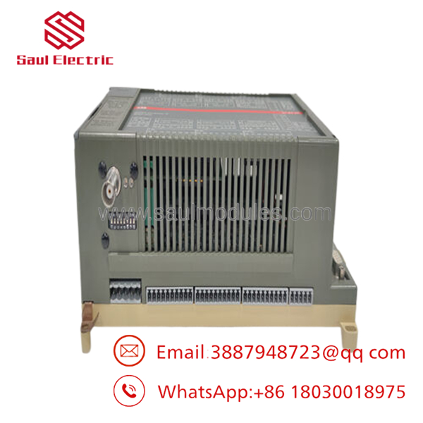
- 07KT94
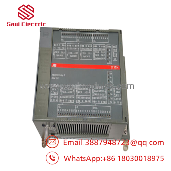
- 07KT94
Installation & Configuration Guide
1.Pre-Installation Preparation:Estimated time: 10 mins.
Isolate localized power lines. Notify operations of the impending control loop shutdown. Turn off and lock out the 24 V DC auxiliary power supply driving the target PLC section.
Verify the power line is dead with a Fluke 115 multimeter before disconnecting components. Ensure you have an ESD grounding wrist strap, a 3.5 mm flathead terminal screwdriver, wire markers, a fresh lithium backup battery (type TA521), and your smartphone.
Connect your laptop to the active controller via the 07SK50 or 07SK52 programming cable and perform an absolute backup of the current application logic and register data maps.
2.Removing the Old Processor:Estimated time: 5 mins.
Attach your grounded ESD wrist strap to the panel chassis. Capture sharp photographs of the terminal structures, noting the location of the CS31 bus wires (terminals 1 and 2) and the serial connection ports.
Unplug the removable terminal blocks carefully by applying steady, even upward pressure to prevent fracturing the plastic housing. Loosen the upper and lower mechanical mounting clips that latch the 07KT94 unit to the DIN rail, then lift the unit clear of the rail assembly.
3.Installing the New Module:Estimated time: 10 mins.
Remove the new 07KT94 from its ESD enclosure. Open the battery compartment hatch and hook up the fresh lithium backup battery to retain variables when power is cycled.
Configuration Clone: Locate the network addressing DIP switch block positioned on the side or rear of the module housing. Using your smartphone photo, mirror the exact configuration of the old unit to set the proper node designation and transmission speed for the CS31 fieldbus.
Snap the unit squarely back onto the DIN rail until you hear the structural latch click. Reattach the terminal block groupings, verifying that no wire strands are loosely hanging out of the pressure clamps.
Self-Checklist:
- [ ] Lithium battery is connected properly under the protective cover flap.
- [ ] DIP switches match the old processor’s network addressing values exactly.
- [ ] Removable terminal blocks are pushed completely flat against the base pins.
4.Power-On & Comms Commissioning:Estimated time: 15 mins.
Verify that there are no short circuits across the 24 V DC terminals (L+ and M) with your multimeter. Apply system power to the basic unit.
Observe the front LED indicators during initialization. The green RUN light should activate, while the red ERR lamp should remain dark. If the BATT LED illuminates, the internal backup battery is missing or depleted.
Establish an active programming connection, verify that the controller firmware matches your baseline configuration, and upload your compiled application code. Cycle the unit from STOP to RUN mode to verify active communication across the remote CS31 I/O nodes.
Frequently Asked Questions (FAQ)
Q: Can I hot-swap the 07KT94 unit while the underlying field network is running?
A: No, you cannot. The 07KT94 acts as the central system controller and fieldbus master. Disconnecting this basic unit while the rack power is active can trigger unexpected voltage variations across the RS-485 communication line, which can damage the serial port interfaces of connected remote I/O nodes or freeze the fieldbus line. Always isolate the 24 V DC supply before attempting to swap this component.
Q: Will I lose my PLC application logic when I remove the old 07KT94 unit?
A: Yes, the running application code and volatile register values reside inside the battery-backed internal RAM of the processor. Once you unplug the unit or detach its internal lithium cell, that data will clear. Therefore, it is critical to save an updated backup copy of your operating software to a programming PC using the AC31 90 Series software utility before taking the old hardware offline.
Q: What is the primary difference between the 07KT94 and the 07KT94-S safety variant?
A: The standard 07KT94 handles basic industrial control sequences and standard automation tasks. The “S” variant (07KT94-S) is an upgraded, high-reliability safety processor built for critical monitoring configurations and safety-instrumented systems. It incorporates specialized safety programming logic and hardware diagnostics designed to comply with rigorous international functional safety regulations. The two variants are not directly interchangeable without re-verifying your software configuration and safety certifications.
Q: What should I check if the ERR LED remains lit after installing the replacement unit?
A: A solid or flashing red ERR light indicates a localized system fault or configuration mismatch. First, confirm that the side DIP switches are configured correctly and that the node address does not conflict with another device on the fieldbus. Next, establish a diagnostic connection through the programming port to check the internal system error flags. This will tell you if the fault is being caused by an analog I/O loop failure, a corrupt internal program line, or an unrecognized hardware component.
Q: Why does the 07KT94 require a dedicated lithium battery if it features Flash EPROM?
A: While the structural control logic and system parameters are saved in non-volatile Flash memory, the internal clock settings, system status flags, and variable data tables are stored in volatile RAM. The lithium backup battery provides continuous low-level power to keep this critical data intact during standard plant shutdowns or unexpected power losses, preventing the system from losing its current status registers when rebooted.

 Start Chat


