





Description
Key Technical Specifications
| Parameter | Value |
|---|---|
| Model | 1TGB302004R5003 |
| Manufacturer | ABB |
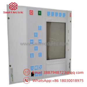
| Product Type | MMI Kit F (Human-Machine Interface Module) |
| System Platform | ABB INSUM Motor Management System |
| Primary Function | Local operation, monitoring, and diagnostics |
| Operating Mode | Parallel operation support |
| Installation | Panel/cabinet mounting |
| Communication | INSUM internal communication bus |
| Weight | Approximately 2.09 kg |
| Application | Motor Control Centers (MCC), process automation |
| Lifecycle Status | Legacy spare part |
Compatibility Note: Available references identify 1TGB302004R5003 as an MMI Kit F for parallel operation used in ABB INSUM motor management systems. Verify the exact INSUM generation, firmware revision, and cabinet configuration before ordering, as hardware variants may not be interchangeable.
Product Introduction
ABB 1TGB302004R5003 is an MMI (Man-Machine Interface) Kit F designed for ABB INSUM motor management systems. The module provides local operator access for equipment monitoring, diagnostics, parameter adjustment, and system operation within intelligent motor control center (MCC) installations.
This module is primarily used as a maintenance spare in existing INSUM installations. During replacement, verify the INSUM controller revision, communication configuration, and application database before commissioning. Hardware replacement alone does not guarantee successful startup if the system configuration differs.
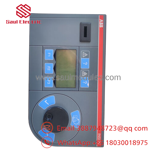
- 1TGB302004R5003
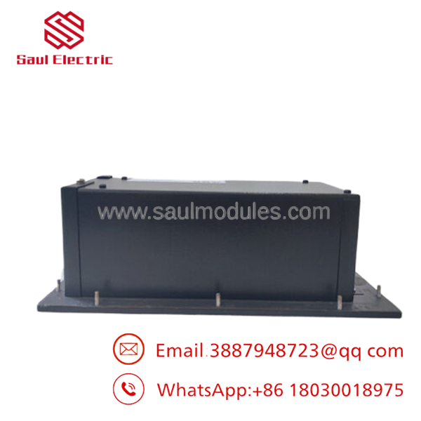
- 1TGB302004R5003
Installation & Configuration Guide
Stage 1: Pre-Installation Preparation (Estimated Time: 10 Minutes)
⚠️ Safety First
- Notify operations of scheduled maintenance.
- Place the MCC in a safe operating condition.
- Apply Lockout/Tagout (LOTO).
- Isolate both control and auxiliary power.
- Wait for all control voltages to discharge.
Tools Required
- Grounded ESD wrist strap
- PH1 screwdriver
- Fluke 115 digital multimeter
- Wire labels
- Smartphone for documentation
Data Backup
- Record the INSUM node configuration.
- Save controller parameters where available.
- Photograph every connector and cable.
- Record communication settings.
- Document module location within the cabinet.
Stage 2: Removing the Old Module (Estimated Time: 10 Minutes)
- Open the cabinet.
- Label all communication and power connectors.
- Disconnect cables carefully.
- Release retaining hardware.
- Remove the module straight from its mounting position.
- Inspect connectors for bent pins, corrosion, or contamination.
⚠️ Retain the original module until the replacement has completed full operational testing.
Stage 3: Installing the New Module (Estimated Time: 10 Minutes)
- Wear an ESD wrist strap.
- Verify the exact model:
- 1TGB302004R5003
- Configuration Clone (Critical)
- Confirm hardware revision.
- Restore communication parameters.
- Verify cabinet addressing.
- Match any jumper or switch settings.
- Install the module securely.
- Tighten mounting hardware.
- Reconnect all wiring.
Self-Checklist
- Correct ABB part number
- Hardware revision verified
- Connectors secured
- Communication settings restored
- ESD procedures followed
Stage 4: Power-On & Testing (Estimated Time: 20–30 Minutes)
Pre-Power Inspection
- Verify auxiliary supply voltage.
- Check connector orientation.
- Ensure no loose hardware remains inside the cabinet.
Power-Up Procedure
- Energize the control system.
- Observe startup indicators.
- Verify communication with the INSUM controller.
- Confirm operator interface functions correctly.
- Test alarm acknowledgement and parameter access.
- Verify communication with connected motor management units.
⚠️ Troubleshooting Note
- No display or response: Check control power and connector seating.
- Communication timeout: Verify INSUM network configuration and node addressing.
- Intermittent operation: Inspect communication cables and grounding before replacing the module.
Frequently Asked Questions (FAQ)
Q1. Can the ABB 1TGB302004R5003 be hot-swapped?
No.
The MMI module should be replaced with the control system powered down. Live replacement can interrupt communication with the INSUM network and may result in configuration or communication faults.
Q2. What is the primary function of this module?
The 1TGB302004R5003 serves as a Man-Machine Interface (MMI) Kit F for ABB INSUM systems, providing local monitoring, diagnostics, and operator interaction with intelligent motor control equipment.
Q3. Is this model still available?
This module is considered a legacy ABB spare part. Most units currently on the market are supplied as New Original, New Surplus, or professionally tested inventory through industrial automation spare-part distributors.
Q4. What should I verify before ordering?
Confirm:
- ABB Part Number (1TGB302004R5003)
- INSUM system generation
- Hardware revision
- Firmware version
- Cabinet type
- Communication configuration
Never order solely by the appearance of the module.
Q5. Why is New Surplus inventory less expensive than factory pricing?
New Surplus units generally originate from cancelled projects, excess OEM inventory, or strategic spare-part stock. Although unused, every module should undergo serial-number verification, visual inspection, power-on testing, and communication validation before shipment.
Q6. What quality inspections should be completed before shipment?
A comprehensive inspection should include:
- OEM serial number verification
- Anti-counterfeit inspection
- Visual inspection for corrosion, scratches, or repair marks
- Power-on functional testing
- INSUM communication verification
- Continuous burn-in testing (24 hours where practical)
- Insulation resistance testing (>10 MΩ where applicable)
- ESD-safe packaging with QC sign-off
Test reports, photographs, and operational videos should be available upon request.
Q7. What is the most common field installation mistake?
Replacing the MMI before checking the INSUM communication network.
I’ve seen engineers replace a perfectly functional MMI because the display appeared offline, only to find the real problem was a failed communication link or incorrect node addressing. Before replacing the hardware, verify network integrity, controller status, and communication diagnostics. Those checks often resolve the issue without changing the module.

 Start Chat


