





Description
Key Technical Specifications
| Parameter | Value |
| Product Type | Rigi Crowbar Drive PCB / Protection Board |
| Model Designation | GD C801 A (GDC801A) |
| Board Revision | 3BHE024748P104 / 3BHE024748P201 Rev. B |
| Voltage Rating | 800 V DC |
| Continuous Current Rating | 100 A |
| Peak Transient Current | ≥ 50 kA (clamping / bypass limit) |
| Response Time | < 1 µs (nanosecond-range trigger) |
| Coating Type | Varnished PCB (industrial environmental protection) |
| Enclosure Rating | IP20 (must be installed inside drive cabinet enclosure) |
| Dimensions (W x H x D) | 120 mm x 100 mm x 20 mm |
| Net Weight | 0.20 kg (0.44 lbs) |
| Operating Temperature | -40 to +70 °C |
Product Introduction
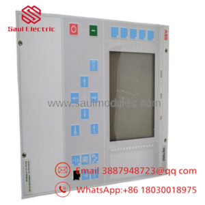
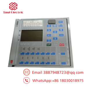
The ABB GD C801 A (3BHE024747R0101) is a specialized, varnished crowbar control board designed specifically for the ACS2000 and ACS5000 medium-voltage variable speed AC drives. Acting as the core component of the drive’s hardware-based protection system, this board handles transient overvoltage events by triggering a low-impedance “crowbar” circuit to safely redirect and bypass excess power grid energy.
Equipped with high-reliability circuitry and boasting ultra-fast triggering response times under 1 microsecond, the 3BHE024747R0101 prevents voltage spikes from reaching the drive’s main inverter modules, silicon-controlled rectifiers, or motor windings. Its factory-varnished PCB protects trace layouts from moisture, conductive particulate matter, and harsh environmental conditions common in marine propulsion, mining, and water pumping installations.
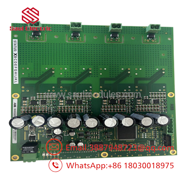
- 3BHE024747R0101
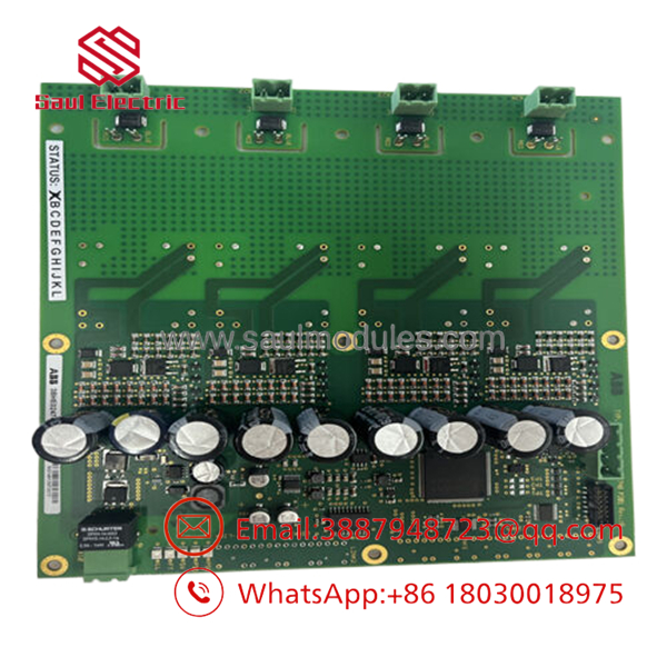
- 3BHE024747R0101
Installation & Configuration Guide
Stage 1: Pre-Installation Preparation (Estimated Time: 15 minutes)
- ⚠️ Safety First: Medium-voltage drive systems (typically 4.16 kV or higher) contain lethal stored electrical energy. Isolate all primary line disconnects. Wait at least 15 to 20 minutes for the DC link capacitors to discharge. Ground the system with certified high-voltage ground hooks. Verify that the busbars are dead using a reliable proximity voltage detector before initiating cabinet access.
- Tools Required: Grounded ESD wrist strap, PH1/PH2 screwdrivers, clean lint-free wipes, electronic contacts cleaner.
- Data Backup: The GD C801 A serves strictly as a physical overvoltage protection controller. There are no firmware parameters or parameter configurations to download to the card. However, executing a full parameters backup on the main drive control hub via DriveComposer is recommended before disabling system power.
Stage 2: Removing the Old Module (Estimated Time: 5 minutes)
- Verify the drive control logic power is turned off.
- Wear your grounded ESD wrist strap and secure its grounding clamp to the frame of the drive cabinet.
- Carefully disconnect any signal cable plugs and gate lead connections hooked directly to the face of the board.
- Remove the mounting screws securing the PCB to its housing baseplate or card frame.
- Slide the 3BHE024747R0101 board straight out of its slot to avoid bending any backplane contact pins.
Stage 3: Installing the New Module (Estimated Time: 10 minutes)
- Unbox the replacement 3BHE024747R0101 card on an anti-static work pad. Do not touch bare copper traces or surface-mount parts.
- Verify that physical key positions or switches on the replacement board match those on the retired board exactly.
- Carefully align the card edges with the designated guide tracks inside the drive unit.
- Gently push the board into the slot until it is fully seated against the backplane connection headers.
- Re-insert and tighten the physical mounting screws to prevent localized vibrations from cracking the PCB.
- Reconnect the logic cables and gate leads, ensuring the terminal connectors are seated and locked.
Self-Checklist:
- [ ] Board aligns perfectly and mounting screws are hand-tightened
- [ ] Multi-pin wiring harnesses and gate cables snap-locked into place
- [ ] Grounding terminal screw checked for clean contact with the frame
Stage 4: Power-On & Testing (Estimated Time: 15 minutes)
- Verify that all diagnostic tools and grounding rods have been removed from the cabinet. Close and lock the drive bay doors.
- Switch on the auxiliary 230 V AC / 24 V DC control power (leaving the main high-voltage isolated).
- Observe the LED status indicators on the drive controller unit and local boards.
- Verify that no “Crowbar Fault,” “Hardware Mismatch,” or “Overvoltage Protection Failure” alarm codes appear on the drive interface display.
- Once the system clears all startup tests, remove standard lock-out pins, safely re-energize the primary medium-voltage line, and conduct a low-speed dry run to verify signal feedback.
- ⚠️ Troubleshooting Note: If the system reports a communication error with the card, shut down the auxiliary power, pull the card, and inspect the backplane pins for misalignment or dust buildup.
Frequently Asked Questions (FAQ)
What is the primary function of a “Crowbar Board” like the GD C801 A?
In medium-voltage drives, a crowbar circuit is a critical protection mechanism. If an overvoltage condition is detected on the DC bus (from grid fluctuations or regenerated energy from a heavy motor load), the GD C801 A instantly triggers a short-circuit pathway (the “crowbar”) to shunt the high voltage away from sensitive power semiconductors. This prevents severe component destruction by safely dumping the excess charge.
Can the 3BHE024747R0101 be swapped while the drive system is running?
Absolutely not. The crowbar board sits directly on the boundary of high-voltage and high-current circuits. Attempting to replace this board while the system is under load or energized can trigger catastrophic high-energy arc flashes, destroy other controller modules on the bus, and present a fatal risk to maintenance personnel. Always follow complete power isolation procedures.
Why does the card have two different part numbers (3BHE024747R0101 and 3BHE024748P104)?
In ABB’s spare parts structure, the number 3BHE024747R0101 refers to the complete, orderable board assembly (often incorporating the varnished coating, specific hardware revision, and installation kit components). The number 3BHE024748P104 (or P201) is the raw printed circuit board (PCB) fabricator identifier silkscreened onto the green board substrate itself. They refer to the same physical part.
Is this board conformal-coated to resist industrial contaminants?
Yes. The GD C801 A features a factory-applied industrial varnishing layer (conformal coating). This protects the delicate micro-electronics, tracking traces, and solder pads from conductive dust, ambient humidity, salty sea air in maritime applications, and chemical vapors, significantly reducing the risk of tracking-fault short circuits over time.
Why is your surplus price more economical than purchasing directly from the factory?
We specialize in sourcing unused, high-quality surplus industrial parts, canceled project orders, and excess warehouse inventories from international operators. Since we bypass conventional dealer markups, we can supply genuine ABB parts at direct savings, providing an immediate, cost-effective avenue to reduce downtime without waiting for lengthy factory backorders.

 Start Chat


